ADR233B
Ref ID : ADR233B/IM/SS
Rev No. : 05
Page No. : 168 of 479
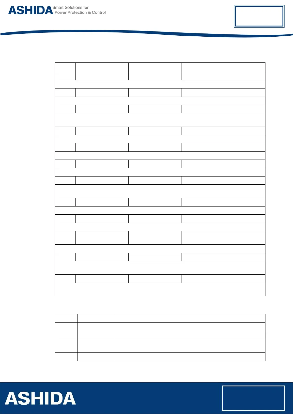
6.2 CB Control (for W1 & W2)
Sr. No Parameter Defaults setting Setting / Ranges
1.
Password 0000 0000 to zzzz/ZZZZ
This setting is to enter the set password
2.
TCS Enable Disabled Disabled / Logic Low / Logic High
This setting is to enable (activate) or disable (turn off) the Trip Circuit Supervision Alarm function
3.
TCS Delay 0.50 S 0.01s to 10s in step of 0.01s
This setting is to set the time-delay for the Trip Circuit supervision if relay detect any discontinuity then
relay generate TCS alarm after set Tsup timer is over
4.
CB Open S'vision Enabled Disabled / Enabled
This setting is to enable (activate) or disable (turn off) the CB Open Supervision function
5.
CB Open Time 300 ms 50 ms to 1000ms in step of 0.01s
This setting is to set the time-delay for CB Open Time monitoring
6.
CB Open Alarm Enabled Disabled / Enabled
This setting is to enable (activate) or disable (turn off) the CB Open Alarm function
7.
CB Oper. Counter 20000 10 to 50000 in step of 1
This setting is to monitor the number of CB Open operation and after set number of CB Open
operations are over the relay give Alarm signal.
8.
CB I Rated 100 1 to 5000A in step of 1A
This setting is used to set rated current of Circuit Breaker.
9.
M constant 1 0.1 to 5 in step of 0.001
This setting is used to set M constant to calculate sigma current.
10.
CB Control By Disabled Disabled / Local / Remote / Local +
Remote
This setting is to select a mode of control, which is used to control the circuit breaker operation.
11.
t CB Open Pulse 0.50 S 00.10 to 50.00 sec in step of 0.01s
This setting defines the duration of the t CB Open Pulse within which the CB should operate when a
manual or control command is issued.
12.
t CB Close Pulse 0.50S 00.10 to 50.00 sec in step of 0.01s
This setting defines the duration of the t CB Close Pulse within which the CB should operate when a
manual or control command is issued.
6.3 REPORTING
Sr. No Parameter Display value on LCD
1. Event Display of all digital events with time stamping
2. Status Display Status of Digital Input & Digital Output
3. Fault Record Display the Records of fault i.e. parameter value, flag of fault & date and
time of Fault
4. Error Log Display of error generated by relay if any, in case of failure of hardware