ADR233B
Ref ID : ADR233B/IM/PS
Rev No. : 05
Page No. : 140 of 479
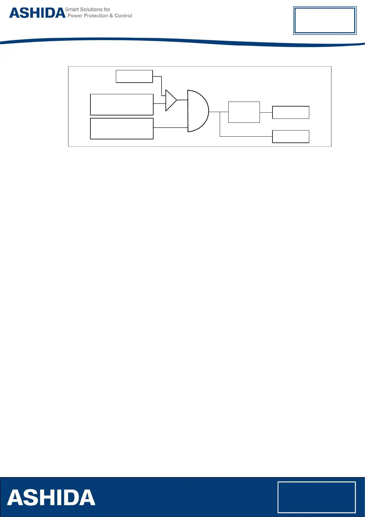
Seq.I>1
+
-
&
I2 Negative
Sequence Current
Seq.I>1 Enable =
-Seq.
Seq.I>1 T
Seq.I>1 P
IDMT/
DT
Figure 18: Logic Diagram for the Negative sequence over current
The Negative phase sequence over Current logic calculate Negative phase sequence current
and checks whether it is exceeds the pickup value (Seq.I>1) and calculate the operating time
based on the curve selected in the Seq.I>1 Curve and Seq.I>1 TMS, Seq.I>1 Time Dial or
Seq.I>1 DT Delay parameter settings. After satisfied all the above condition the IED generates
Negative Phase over current trip. Once the Pickup signal will be asserted then it will reset after
the time delay calculated from IDMT/DT dropout characteristics.
The Positive sequence current logic also works similar as Negative sequence current but, the
measured quantity is positive sequence current.
4.13 IDMT Characteristics
ADR233B relay provides inverse time over current characteristic for W1/ W2 phase over current,
ground over current, Residual Over Current elements and sequence over current. Each stage is
independently settable with inverse time or definite time characteristic. The following IDMT
characteristics are available
• IEC Standard Inverse Curve
• Standard Time Inverse 1.3s Curve
• IEC Very Inverse Curve
• IEC Extremely Inverse Curve
• UK LT Inverse Curve
• Definite time Over current
• IEEE Moderately Inverse Curve
• IEEE Very Inverse Curve
• IEEE Extremely Inverse Curve
• US Inverse Curve
• US ST Inverse Curve