ADR233B
Ref ID : ADR233B/IM/SS
Rev No. : 05
Page No. : 174 of 479
This setting is to set the blocking time delay for the transformer differential protection
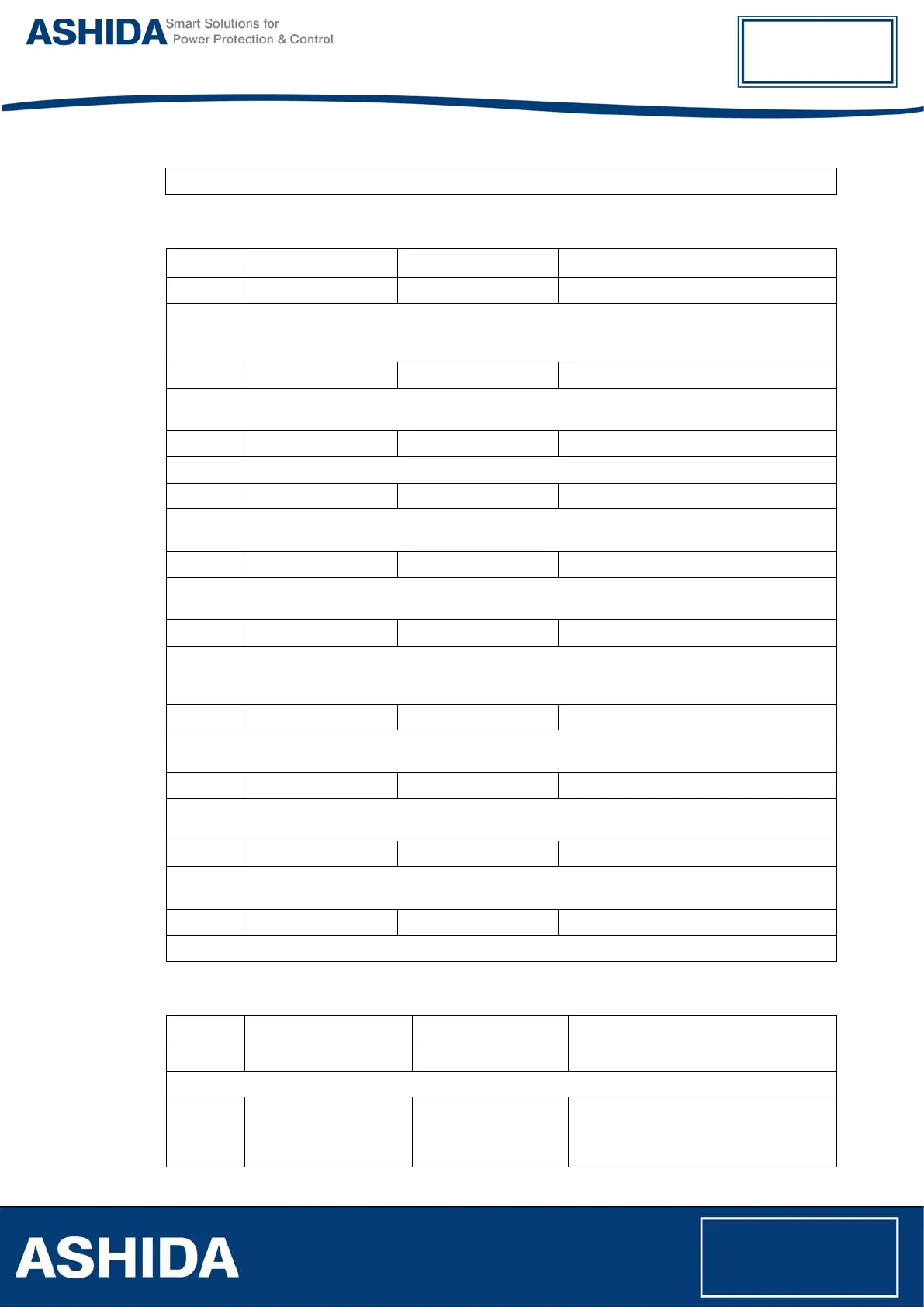
6.8.3 REF
Sr. No Parameter Defaults setting Setting / Ranges
1. REF Enable LowZ REF Disabled / Low Z / High Z
This setting is to disable REF or select the type of REF to be used (i.e. Low Impedance or High
Impedance) for the HV winding. Based on selection of REF HV status, the relevant settings is only
visible, All others settings are invisible.
2. Isr> 0.09 A 0.05 to 1 in step of 0.01 A
Minimum differential threshold of the HighZ restricted earth fault protection. This setting is visible only if
REF status is selected as HighZ REF.
3. Ref. Winding W2 W1 / W2
This setting is to set the reference winding use for calculation of Low Z REF
4. Isr>1 0.10 pu 0.05 pu to 1.00 pu in step of 0.01pu
This setting is to set the minimum differential current threshold required for the REF protection to trip.
This setting is visible only when REF status is selected as LowZ REF.
5. Isr>2 0.1 pu 0.1 pu to 10.0 pu in step of 0.1pu
This setting
defines the bias current threshold at which the second slope of the bias current characteristic
becomes active for the REF protection. This setting is visible only if REF status is selected as LowZ REF.
6. Slope1 0% 0% to 150% in step of 1%
This setting defines the first slope in the bias current characteristic for the REF protection. A 0% setting
gives maximum sensitivity for internal faults. This setting is visible only if REF status is selected as LowZ
REF.
7. Slope2 150% 15% to 150% in step of 1%
This setting defines the second slope in the bias current characteristic for the REF protection. This
setting is visible only if REF status is selected as LowZ REF.
8. tIsr> 0.00 S 0s to 10s in step of 0.01s
This setting is to set the time delay for the REF protection element. This setting is visible only if REF
status is selected as LowZ REF.
9. 2nd Hrm REF BLK Disabled Enabled or Disabled
This setting is to enable or disable the second harmonic blocking for the element. This setting is visible
only if REF status is selected as HighZ REF or LowZ REF.
10. 2ndHrm Threshold 20% 5% to 70% in step of 1%
This setting is to set 2nd harmonic threshold, if REF
6.8.4 Phase OC (W1 & W2)
Sr. No Parameter Defaults setting Settings / Ranges
1. IP>1 Enable Disabled Disabled/Enabled
This setting is to disable or enable the Phase over current protection function.
2. IP>1 Curve IEC S Inverse Definite Time / IEC S Inverse / ST
Inverse 1.3S / IEC V Inverse / IEC E
Inverse / UK LT Inverse / IEEE M
Inverse / IEEE V Inverse / IEEE E