ADR233B
Ref ID : ADR233B/IM/PS
Rev No. : 05
Page No. : 144 of 479
4.13.1 Timer Hold Facility / Reset Characteristics
All stages of Phase OC, Ground OC (EF), Residual OC (3Io) and Sequence OC protection is
provided with a timer hold facility "D/O Char". It can be programmed as a definite time or IDMT.
A possible situation arises where the reset timer may be used to reduce the fault clearance time
where intermittent faults occur.
For example, a cable with plastic insulation application, it is possible that the fault energy melts
the cable insulation, which then reseals after clearance, thereby eliminating the cause for the
fault. This process repeats itself to give a succession of fault current pulses, each of increasing
duration with reducing intervals between the pulses, until the fault becomes permanent.
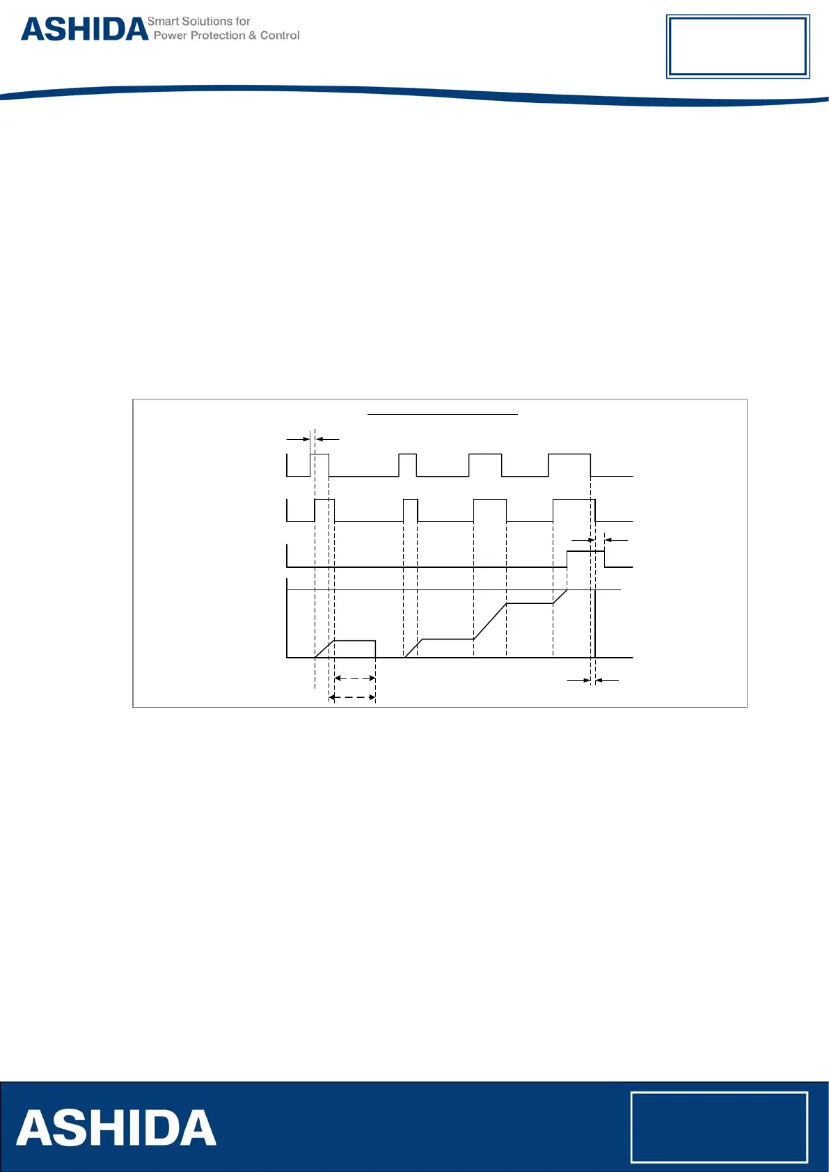
Following diagram explain the function of definite time reset characteristic
Definite Time Reset Characteristic
Start Time
Energising
Quantity > Gs
Start (Pick-up)
Signal
Operated
Signal
Value of
Internal Time
delay counter
tr Reset time settings
Reset Time
Restart Time
Time Delay setting
Tripping
Disengaging
Time
Figure 21: Definite Time Reset Characteristic
For IDMT reset characteristic following formula:
t = RTMS x K
--------------------
(I / Is)
α
Where
t = Reset time
K = Factor (see table)
I = Value of the measured current
Is = Value of the programmed threshold (pick-up value) (also refer as Gs as IEC
standard notation)
α = Factor (see table)
RTMS Reset time multiplier (RTMS) setting between 0.025 and 1.2