ADR233B
Ref ID : ADR233B/IM/PS
Rev No. : 05
Page No. : 135 of 479
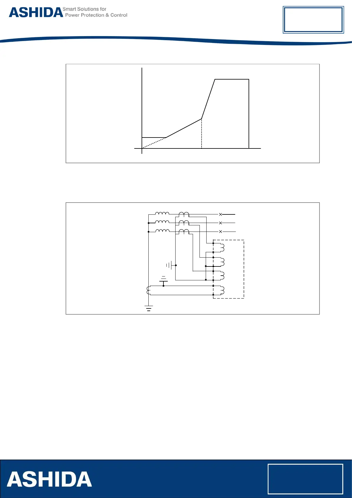
W1 REF Idiff
W1 Isr>1
Operate
Region
Restrain
Region
W1 Isr>2
W1 Slope1
W1 Slope2
W1 REF Ibias
Figure 10: Percentage biased Differential Characteristics for LoZ REF function
The electrical connection diagram for the low impedance is shown below; the current from the
Low impedance REF CT can also be used for standby earth fault function.
A
B
C
In1
Phase CT
REF CT
Phase A
Phase B
Phase C
Figure 11: CT Connection Diagram for low Impedance REF Application
High Impedance REF
The restricted earth fault relay is high impedance differential scheme which balance the zero
sequence current flowing in the transformer neutral against zero sequence current flowing in
transformer phase windings. Any unbalance in-zone fault will result in an increasing voltage on
the CT secondary and thus will activate the REF protection.
The high impedance differential technique ensures that the impedance of the circuit is of
sufficiently high so that the differential voltage that may occur under external fault conditions is
lower than the voltage required driving setting current through the relay. This ensures stability
against external fault conditions and then the relay will operate only for faults occurring inside
the protected zone.