Summary of all Parameters
Parameter manual b maXX BM3000
Document no.: 5.12001.07
791
of 820
6
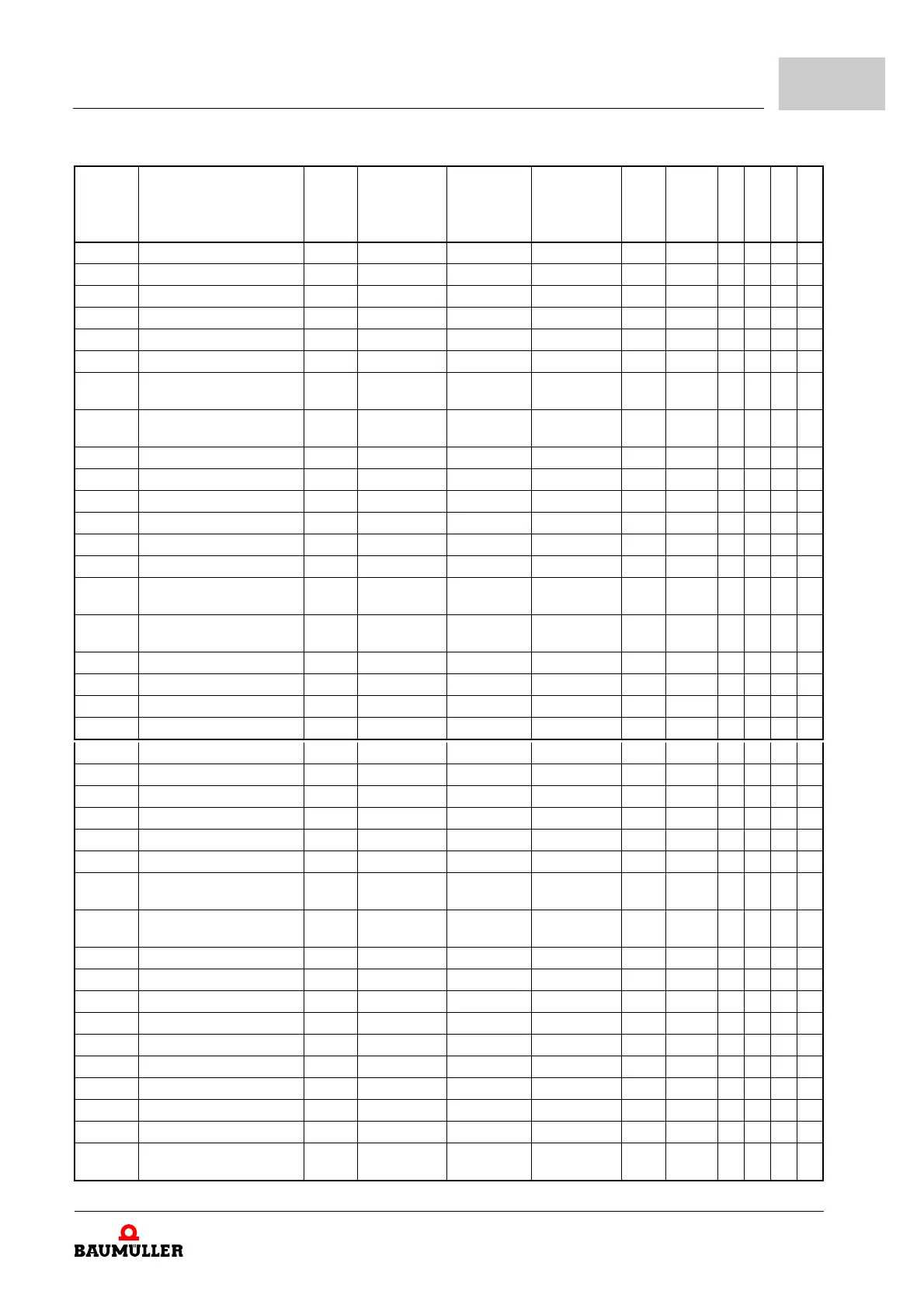
Number Name Type Min Max Default Value Unit Factor
Read only
Storage
DS Support
Cyclic Write
129.19 Peak current 16 kHz FLOAT 0 1000.0 4.0 A 1:1
129.20 Overcurrent threshold FLOAT 0 2000.0 16.6 A 1:1
129.21 Max. DC-link voltage FLOAT 10 1000.0 835.0 V 1:1
129.22 Max peak current time UINT 0 0xFFFF 10,00 s 100:1
129.24 Max phase error delay time UINT 0 0xFFFF 0 ms 1:1
129.25 Current phase error FLOAT 0 1000.0 0 A 1:1
129.26 Max heat sink temperature UINT 0 0xFFFF 85 Grad
C
1:1
129.27 Max interior temperature UINT 0 0xFFFF 65 Grad
C
1:1
129.41 Max. ground current FLOAT 0.16 33.0 3.0 A 1:1
129.42 Min. DC link voltage FLOAT 10 1000.0 10.0 V 1:1
129.49 Amp article number UDINT 0 0xFFFFFFFF 0 1:1
129.50 Chopper resistance FLOAT 0 0xFFFFFFFF 100 Ohm 1:1
129.51 Chopper peak power FLOAT 0 0xFFFFFFFF 1200 W 1:1
129.52 Chopper PT1 model gain FLOAT 0 0xFFFFFFFF 1.4 1:1
129.53 Chopper PT1 model time
constant
FLOAT 0 0xFFFFFFFF 7.5 1:1
129.55 Chopper maximum tempera-
ture
FLOAT 0 0xFFFFFFFF 180 °C 1:1
129.85 Charging blocking time UINT 0 0xFFFF 10 s 1:1
129.86 Peak current 2 kHz TM FLOAT 0 1000.00 10.00 A 1:1
129.87 Peak current 4 kHz TM FLOAT 0 1000.00 10.00 A 1:1
129.88 Peak current 8 kHz TM FLOAT 0 1000.00 10.00 A 1:1
130.1 Heat sink temperature FLOAT 0 1000 0 °C 1:1 X
130.2 Interior temperature FLOAT 0 1000 0 °C 1:1 X
130.3 DC link voltage FLOAT 10 1000 10 V 1:1 X
130.8 Mains voltage FLOAT 0.0e+0 1000 0.0e+0 V 1:1 X
130.9 Fan mode UINT 0x0000 0x0003 0x0001 1:1 X
130.10 Mode UINT 0x0000 0xFFFF 0x0000 1:1 X
130.12 Heatsink temperature war-
ning threshold
UINT 0 0xFFFF 75 °C 1:1 X
130.13 Interior temperature warning
threshold
UINT 0 0xFFFF 55 °C 1:1 X
130.15 PWM frequency UINT 2 16 8 kHz 1:1 X X
130.18 I offset phase U FLOAT -2.56e+02 2.56e+02 0.0 A 1:1.414 X
130.19 I offset phase V FLOAT -2.56e+02 2.56e+02 0.0 A 1:1.414 X
130.20 I offset phase W FLOAT -2.56e+02 2.56e+02 0.0 A 1:1.414 X
130.24 Phase error delay time UINT 0 65535 0 ms 1:1 X
130.25 Mains failure delay UINT 0 6000 0 ms 1:1 X
130.29 Chopper threshold FLOAT 400 780 780 V 1:1 X
130.34 Status STO module UINT 0 0xFFFF 0 1:1 X
130.35 Mains failure detection mode UDINT 0 0xFFFFFFFF 0 1:1 X
130.36 Relative Udc threshold for
mains failure
FLOAT 10 90 80 % 1:1 X
 Loading...