INSTALLATION AND STARTUP
1MANUL220 Belanger, Inc.® * PO BOX 5470 * Northville, MI 48167-5470 * Ph (248) 349-7010 * Fax (248) 380-9681 15-5
Chapter 15 Wheel Cleaning and CTA Options
Wheel Stingers® and Freestanding CTA – Installation of a Bell Hose
8) The Bell Hose is to be secured to the floor before the designated equipment. The Bell Hose
is only across half the bay since only one tire is required to run over the hose to activate it.
Note: Depending on the reaction time of the device, the distance between the sensor and the device it
activates may change. Refer to the individual sensing component manuals for more details.
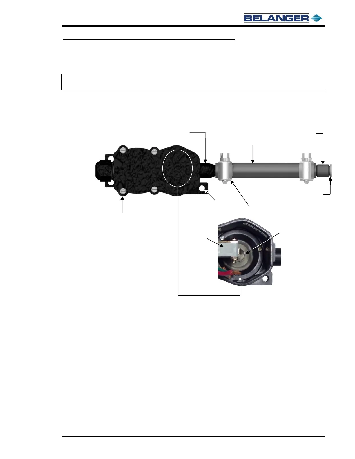
Utility Connections
1) The Bell Hose that you just mounted now must be connected to the pressure switch inlet
port. The hose compresses each time a vehicle runs over it. The resulting displacement of
air moves the diaphragm within the pressure switch enclosure. See the images below.
2) The pressure switch should be mounted to the wall so that a 1/4” poly-flow tube can be
connected to the hose port. The switch should be mounted in a back room. The 1/4” poly-
flow tube will push up into the inside of the hose port on the pressure switch enclosure.
The other end of the tube is to be connected to the air fitting on the Bell Hose mount. See
the image above.