INSTALLATION AND STARTUP
15-6 Belanger, Inc.® * PO BOX 5470 * Northville, MI 48167-5470 * Ph (248) 349-7010 * Fax (248) 380-9681 1MANUL220
Chapter 15 Wheel Cleaning and CTA Options
Wheel Stingers® and Freestanding CTA – Installation of a Bell Hose
Wiring Connections
1) Identify all applicable local codes.
2) Run a field supplied cord that is rated for the application and complies with local codes
in your area from the Wheel Sensor Timer Box for a non-tire tracking controller or from
an input on your system controller if it does have tire tracking to the pressure switch
enclosure. Wire it to be normally open. See the wiring diagram provided with the Air
Panel.
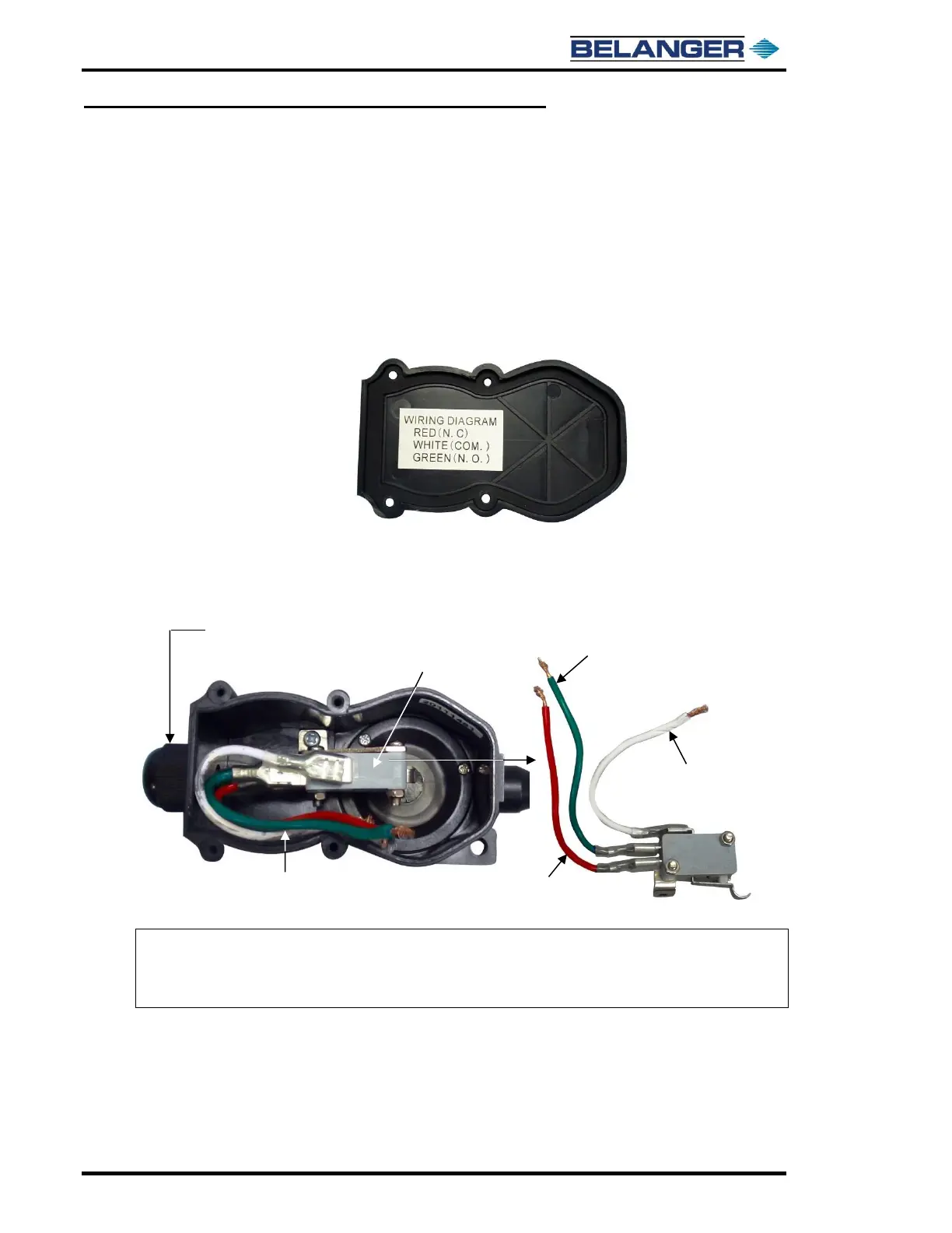
3) Locate the wiring diagram, shown below, supplied on the inside cover of the pressure
switch.
4) Make all necessary wiring connections inside the Pressure Switch Enclosure using the
cord in step 2 and the included connection wires, shown below. Refer to the wiring
diagram inside the pressure switch enclosure, shown above in step 3, and the included
electrical schematic.
Note: A tire sensing device is typically used to trigger input on the optional system tunnel controller
or wheel sensor timer. See the system tunnel control prints and manual when a bell hose is
used with the controller to track tires. See the wheel sensor timer prints when a bell hose is
used with a wheel sensor timer instead.