INSTALLATION AND STARTUP
15-10 Belanger, Inc.® * PO BOX 5470 * Northville, MI 48167-5470 * Ph (248) 349-7010 * Fax (248) 380-9681 1MANUL220
Chapter 15 Wheel Cleaning and CTA Options
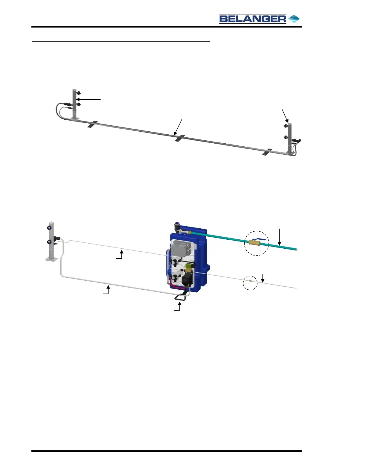
Wheel Stingers® and Freestanding CTA - Utility Connections
Applicators
3) Run 1/2” and 1/4” poly-flow tubes from the tees of the Primary Applicator through the cross
over tube to the Secondary Applicator mount across the bay.
MixStir® Holding Tank and Delivery Pumping Panel
1) Install a field supplied 3/4” ball valve from the main inlet water line and into the Hydro-
Minder inlet. There should be a flexible hose between the main supply line and the inlet on
the Hydro-Minder. See the image below.
2) Install a field supplied 1/4” ball valve to the field supplied main air line that will connect to
the inlet of the electric valve on the delivery pumping panel. This line will supply
compressed air to the air pump and foam air regulator. See the image below.
See Nozzle Chart at the end of this chapter for more details.
1/2" Poly-Flow Tube from the Air
Pump Inlet (Behind the Factory
Installed Red 3/8” Hose) to the
Tee on the Bottom of the Hydro-
Minder™ Tank