INSTALLATION AND STARTUP
4-10 Belanger, Inc.® * PO BOX 5470. * Northville, MI 48167-5470 * Ph (248) 349-7010 * Fax (248) 380-9681 1MANUL220
Chapter 4 Frame and Carriage Assembly
Carriage Prep
Raising the Carriage
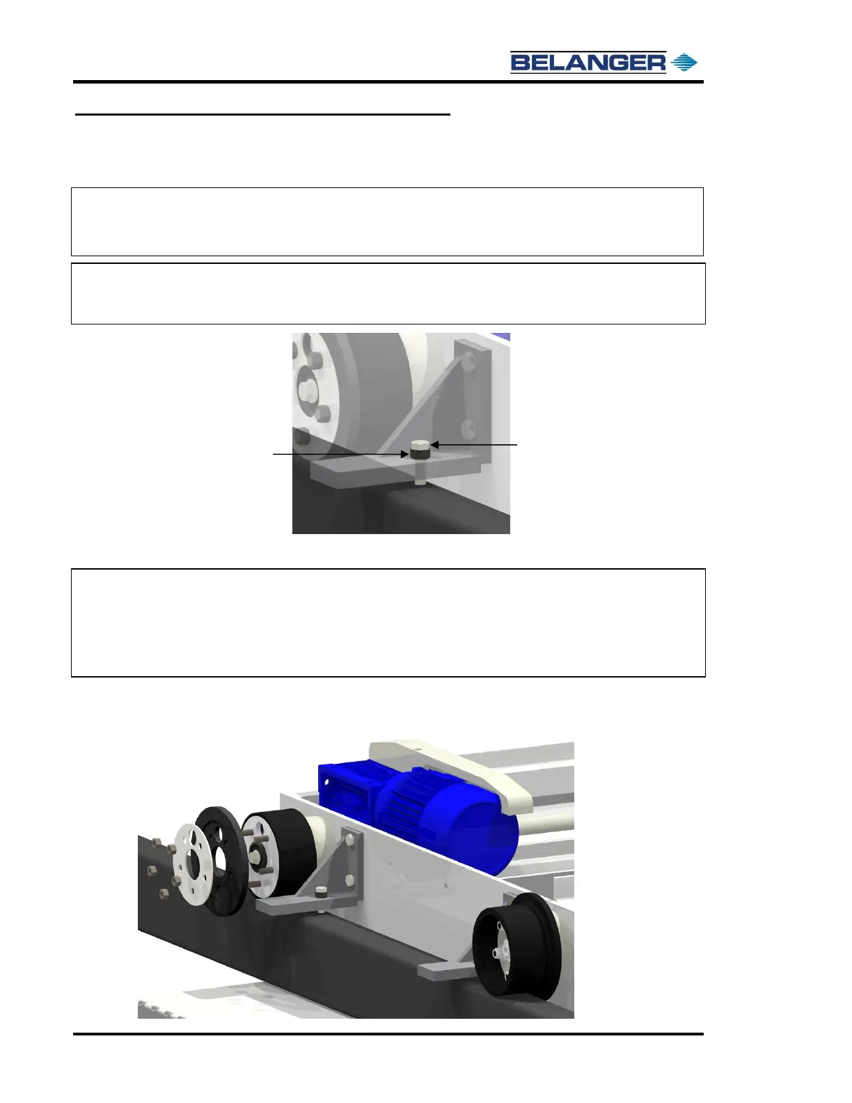
Note: The carriage is equipped with four Jack Bolts that will slightly raise the rollers off
the rails for various maintenance procedures and adjustments to the spacing of the
beams. See the images below for instructions on using the jack bolts.
Adjusting the Rails
Note: If the rails need to be slightly moved to achieve the required 100” spacing, one or
both exit roller caps will have to be removed, allowing the beam to be slightly
repositioned under the roller.
Note: There also may be a need to remove the roller end caps to place the carriage onto the
rails if your site has limited ceiling clearance.
Follow the steps below to remove the caps.
1) Remove the 5 roller nuts and the two-piece roller cap.
Note: The forklift considerations for the carriage are as follows: load weight of the
carriage is 2,250 lbs., load is 136” wide, load center is 40”, and the load needs to be
lifted 72” high.