Parameter descriptions
463 Activity after positioning
The behavior of the positioning after the required position of the drive is reached can be defined via
parameter
Activity after positioning 463.
Activity after positioning 463
0 -
End positioning
The drive is stopped with the stop-ping behavior of Operation
mode 630. In this setting only the second digit of Operation
mode
630 is evaluated. If the state “Hold” is selected, this state
is considered, all other states will result in state “Switch Off”.
1 -
Waiting for positioning sig-
nal
The drive is stopped until the next signal edge; with a new edge
of the position signal, it is accelerated in the previous direction
2 -
Reversal by new edge
The drive is held until the next signal edge; with a new edge of
the position signal, it is accelerated in the opposite direction of
3 -
Positioning; off
The drive is stopped and the power output stage of the inverter
is switched off.
4 -
Start by time control
The drive is stopped for the Waiting Time 464; after the waiting
time, it is accelerated in the previous direction of rotation.
5 -
Reversal by time control
The drive is stopped for the Waiting Time 464; after the waiting
time, it is accelerated in the opposite direction of rotation.
464 Waiting Time
The position reached can be maintained for the
Waiting Time 464, then the drive is accelerated ac-
cording to operation mode 4 or 5.
No. Description Min. Max. Fact. sett.
464 Waiting Time 0 ms 3600000 ms 0 ms
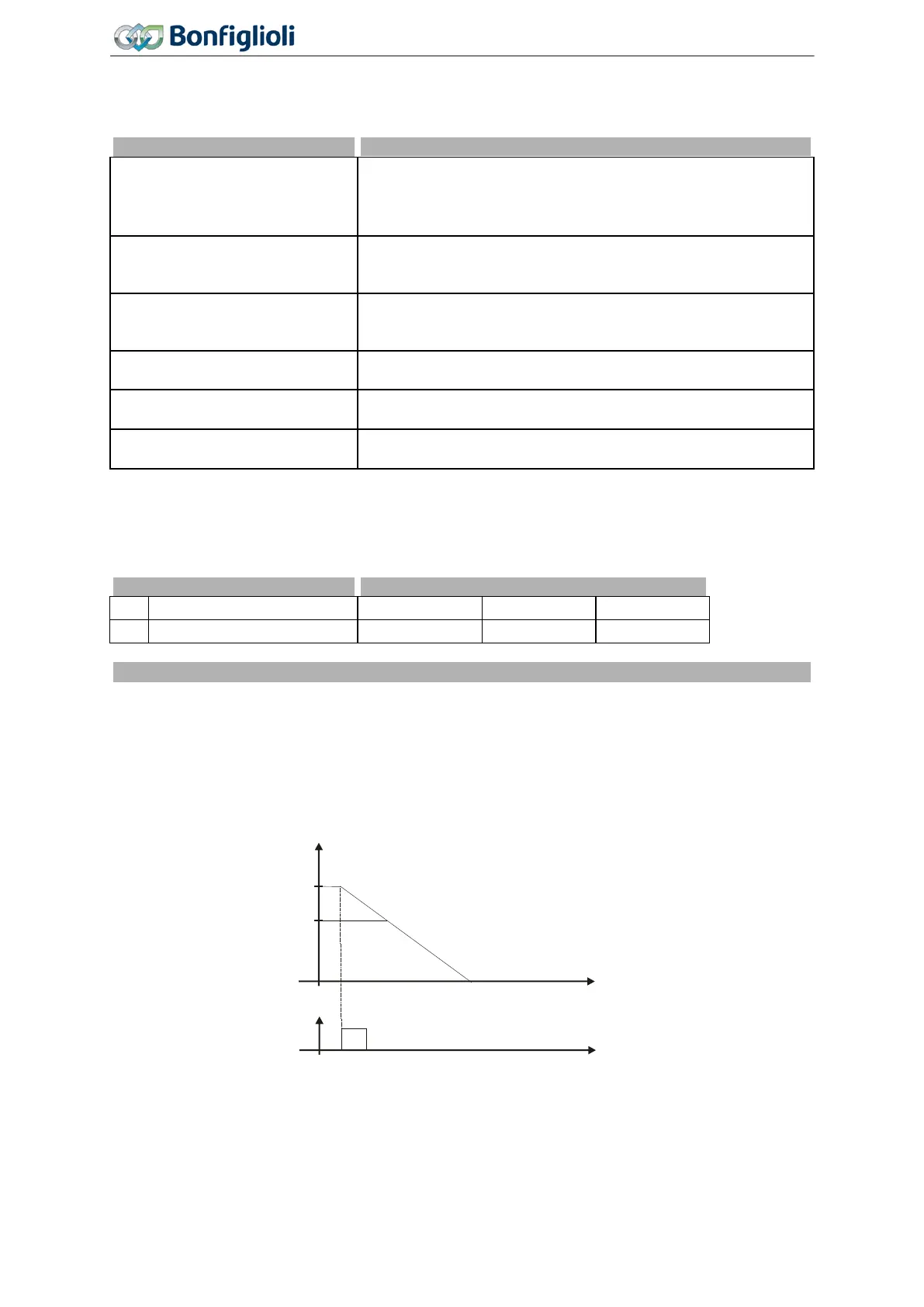
Positioning, Operation Mode 458 = 1
The diagram shows how the positioning to the set positioning distance is effected. The positioning
distance remains constant at different frequency values. At the reference point, the position signal
S
Posi
is generated. Starting from frequency f
max
, the positioning is effected at the set Deceleration
(clockwise)
421. At a lower frequency value f
1
, the frequency remains constant for some time before
the drive is stopped at the set deceleration.
If, during acceleration or deceleration of the machine, positioning is started by the signal S
Posi
, the
frequency at the time of the positioning signal is maintained.
Examples of reference positioning as a function of the parameter settings selected:
− The reference point is identified by a signal at digital input IN1D (terminal X11.4).
f
f
max
f
1
S
posi
U
U
min
t
Digital input IN1D
Deceleration (clockwise)
421
134
Operating Instructions
Agile
06/2013 Operational Behavior

 Loading...


