Parameter descriptions
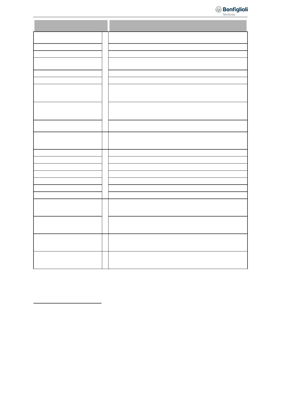
525 -
Inverter Re-
lease(Hardware)
1
Enable signal of the frequency inverter via digital inputs STOA
(X11.3) and STOB (X13.3).
526 -
IN1D (Hardware) Signal at digital input IN1D (X11.4).
527 -
IN2D (Hardware) Signal at digital input IN2D (X11.5).
528 -
IN3D (Hardware)
Signal at digital input IN3D (digital input/output, X11.6) in Op-
eration Mode Terminal X11.6 558 = "0 - Input IN3D".
529 -
IN4D (Hardware) Signal at digital input IN4D (X12.1).
530 -
IN5D (Hardware) Signal at digital input IN5D (X12.2).
531 -
MFI1D (Hardware)
Signal at multifunction input MFI1 (X12.3) in Operation Mode
MFI1 452 "3 - Digital NPN (active: 0 V)" or "4 - Digital PNP
532 -
MFI2D (Hardware)
Signal at multifunction input MFI2 (X12.) in Operation Mode
MFI2 562 "3 - Digital NPN (active: 0 V)" or "4 - Digital PNP
537 to 544
Operation modes 525 to 532 of the digital inputs inverted (LOW
active).
to
to
2
Process data for Profibus communication. Optional communica-
tion module CM-PDP-V1 with Profibus interface is required.
700 -
RxPDO1 Boolean1
3
Process data object for system bus communication.
701 -
RxPDO1 Boolean2 Process data object for system bus communication.
Process data object for system bus communication.
Process data object for system bus communication.
Operation modes 700 to 703 for RxPDO2.
Operation modes 700 to 703 for RxPDO3.
Signal of system bus communication.
to
Obj 0x3003 DigOut 1 to
Obj 0x3003 DigOut 5
4
Sources of CAN objects for CANopen® communication.
to
Out 1 to Obj 0x3005
Sources at output of demultiplexer for CANopen® communica-
tion.
to
to
5
Bit 0 to Bit 15 on output of de-multiplexer; de-multiplexed pro-
cess data signal via system bus or Profibus on input of multi-
plexers (parameter DeMux Input 1253).
to
to
6
Output signals of PLC-functions.
1
The digital signal is independent from the configuration of the parameter Local/Remote 412.
2
Refer to instructions on Profibus.
3
Refer to instructions on system bus.
4
Refer to instructions on CANopen.
5
Refer to instructions on system bus or Profibus.
6
Refer to application manual PLC.
199
Control inputs and outputs 06/2013 Operating Instructions
Agile

 Loading...


