Parameter descriptions
The frequency inverter reacts to the signals at the control inputs both when the power
failure regulation is switched on and in normal operation. A control via externally sup-
plied control signals is only possible in the case of a no
-break supply. As an altern
a-
tive, supply of the control signals through the frequenc
y inverter is to be used.
Output signals
Mains failure and mains support are signaled via digital signals.
Failure of mains voltage and mains support– selected via Operation Mode
670 of the voltage controller.
1)
For linking to frequency inverter functions.
2)
For output via a digital output. Select the signal source for one of the parameters 531, 532, 533,
554. See chapter 7.6.5 "Digital outputs".
Operation mode power failure regulation
Voltage controller: Parameter Operation mode 670 = 2
with Mains resumption
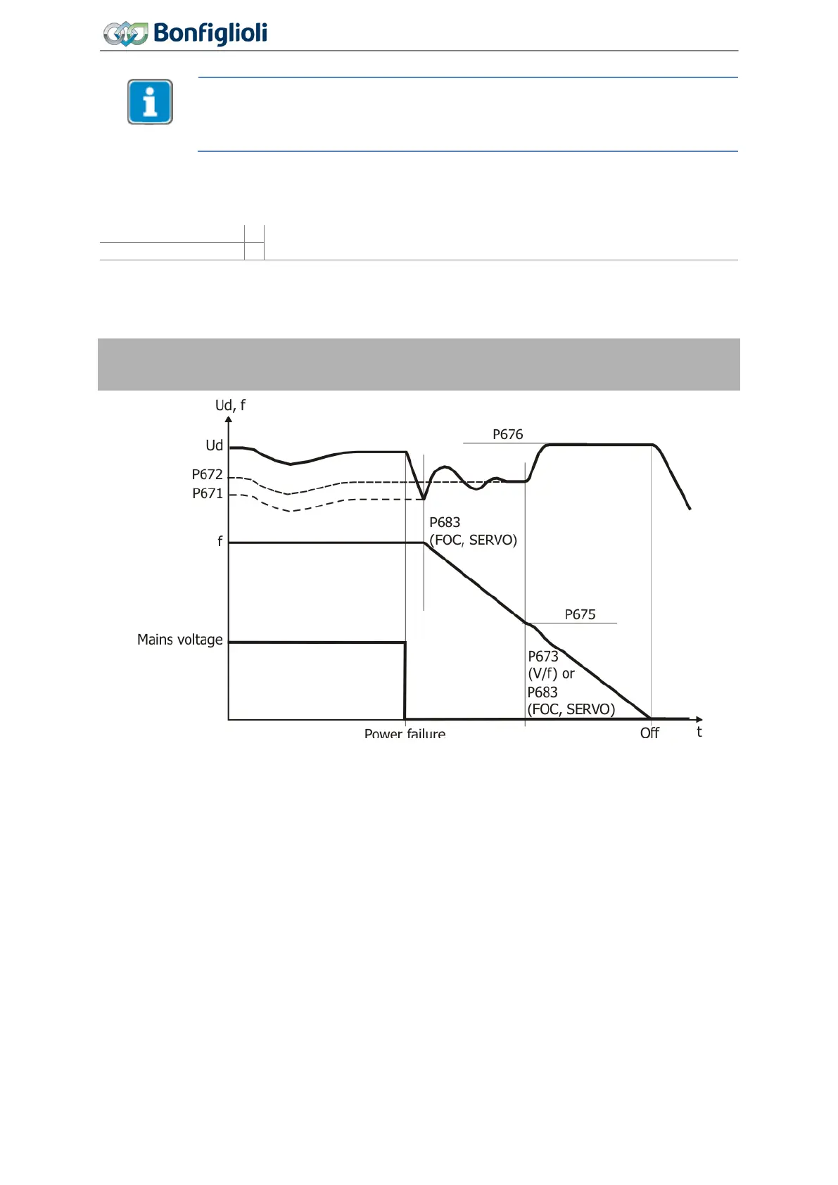
675
Shutdown Threshold
676 Reference Shutdown Value
The DC link voltage which is available in the case of a power failure is supplied by the motor. The
output frequency is continuously reduced and the motor with its rotating masses is switched over to
generator operation. The reduction of the output frequency is done with a maximum of the current
set by the parameter
Gen. Ref. Current Limit 683 or the ramp Mains Support Deceleration 673.
Mains Support Deceleration 673 is only active if the Actual frequency is smaller than Shutdown
Threshold
675.
The time required until the motor has come to a standstill results from the regenerative energy of the
system which results in an increase in the DC link voltage. The DC link voltage set with the parameter
Reference Shutdown Value 676 is used by the voltage controller as a control figure and kept con-
stant. The voltage rise enables optimization of the braking behavior and the time until the drive has
come to a standstill. The behavior of the controller can be compared to stopping behavior 2 (Shut-
down and Stop), as the voltage controller brings the drive to a standstill at the maximum deceleration
ramp and supplies it with the remaining DC link voltage.
If the DC-link voltage is restored before the shutdown of the drive, but after falling below
Shutdown
Threshold
675, the drive is still decelerated to standstill.
218
Operating Instructions
Agile
06/2013 Control functions

 Loading...


