Parameter descriptions
480 Fixed Frequency 1 (in case of missing PID real value)
If the PID real value is missing (<0.5%), the output frequency is guided to the value of
Fixed Fre-
quency 1
480. The minimum value monitoring prevents an acceleration of the drive if the PID real
value is missing. If the PID real value is available again, the controller continues operation automati-
cally.
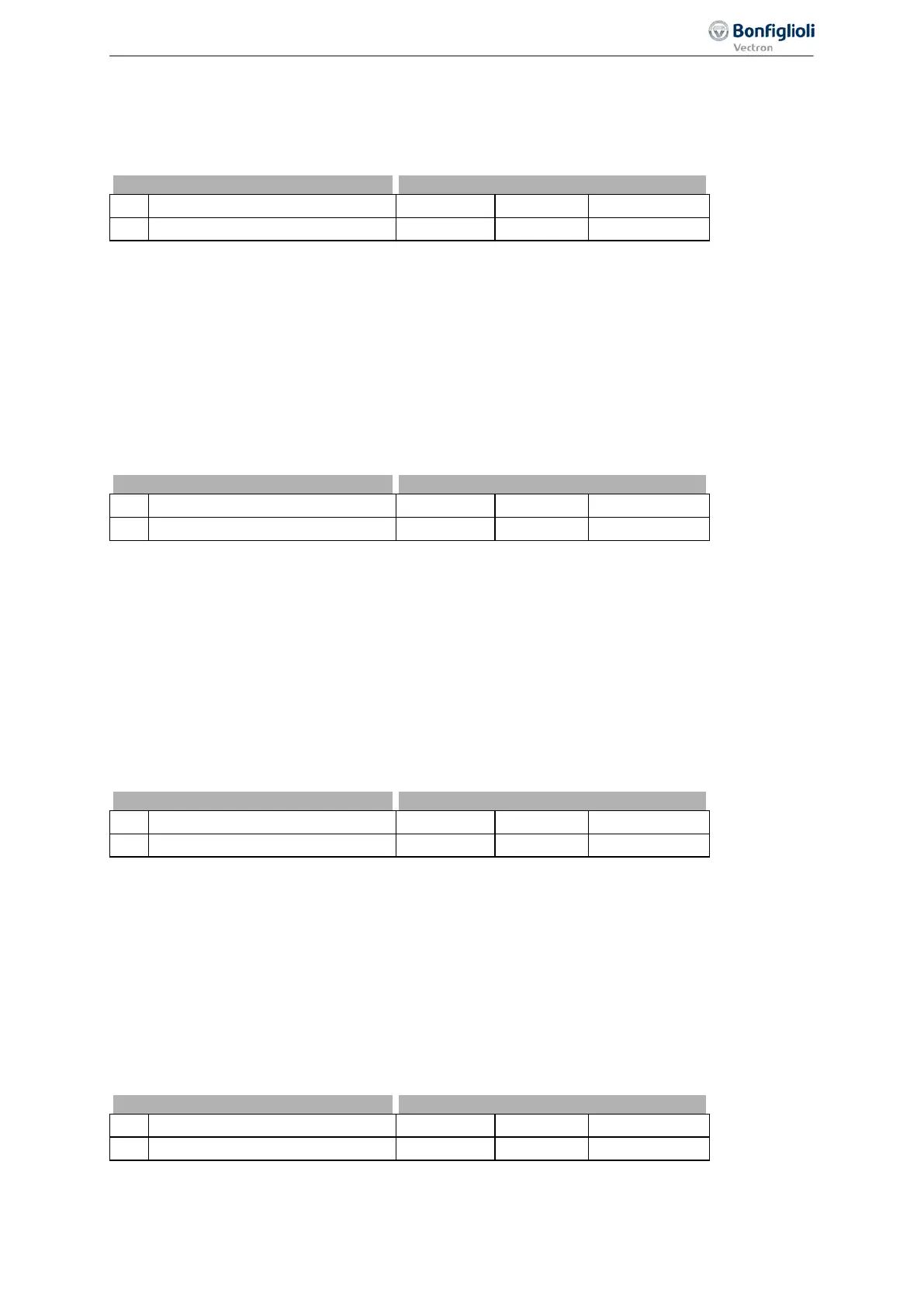
No. Description Min. Max. Fact. sett.
480 Fixed Frequency 1 -999.99 Hz 999.99 Hz 0.00 Hz
The Fixed Frequency 1 480 must be in the range between Minimum Frequency 418 and Maximum
Frequency
419. If the Fixed Frequency 1 480 is set to a value smaller than the Minimum Frequen-
cy
418, the output frequency is guided to Minimum Frequency 418. The frequency will not drop
below
Minimum Frequency 418.
444 Amplification (P)
Parameter
Amplification 444 defines the amplification factor by which the control deviation is multi-
plied. The control deviation can be reduced by large amplification values, but very high values may
cause the control circuit to become unstable (vibrations). If the value is set too low, large control de-
viations are possible.
444 Amplification -15.00 +15.00 1.00
The sign of the amplification defines the control direction, i.e. if the PID real value increases and the
sign of the amplification is positive, the output frequency is reduces (e.g. pressure control). With a
rising PID real value and negative sign of the amplification, the output frequency is increased (e.g. in
temperature control systems, refrigerating machines, condensers).
445 Integral Time (I)
Parameter
Integral Time 445 defines the time constant for calculation of the integral of the PID input
signal. The I controller totals the control deviation over time and divides the result by the value of
Integral Time 445. If the Integral Time 445 is set to small values, the control deviation is compen-
sated quickly. Very low values for the
Integral Time 445 may cause the control circuit to become
unstable (vibrations).
No. Description Min. Max. Fact. sett.
445 Integral Time 0 ms 32767 ms 200 ms
If parameter Integral Time 445 is set to zero, the I controller is deactivated.
The amplification (P) is included in the calculation of the integral time (I), see figure PID controller.
BONFIGLIOLI recommends setting the
Integral Time 445 to a value greater than the sampling time,
which is 2 ms in the case of the
Agile
device.
441 Max. I-Component
Parameter
Max. I-Component 441 defines the maximum output signal of the I-controller. In applica-
tions with quickly changing load torques, vibrations of the control circuit are possible. In order to
avoid vibration, parameter
Max. I-Component 441 can limit the output signal of the I-controller.
225
Control functions 06/2013 Operating Instructions
Agile

 Loading...


