Parameter descriptions
61 – I²t, Multi-Motor Operation,
Warning and Error Switch Off
The I²t capacity of the motors regarding their relat-
ed ratings is monitored in each of the four data
sets. If the Warning Limit Motor I
2
t 615 is reached,
the warning message "A0200" is signaled from the
active data set. If the fixed threshold values exceed
100%
motor
(120%
stator
), the
fault "F0401" in the active dataset. Both incidences
are triggered from the active dataset.
Warning and Error Switch Off
The I²t capacity of the motor is monitored with rat-
ed values from the active dataset.
If the Warning Limit Motor I
2
t 615 is reached, the
warning message "A0200" is signaled from the ac-
tive data set. If the fixed threshold values exceed
100%
motor
(120%
stator
), the drive switches off with
fault "F0401" in the active dataset. Both incidences
are triggered from the active dataset.
608 Thermal time constant motor
609 Thermal time constant rotor
615 Warning limit motor I
2
t
The thermal time constant of the motor is in the range from few minutes to a couple of hours.
This motor-specific parameter is set via
T
hermal time constant motor 608.
Substantially smaller is the thermal stator time constant. To protect the stator winding additional mon-
itoring is required which is determined by
Thermal time constant stator 609.
These values can be taken from the corresponding motor data sheets.
When estimated time constants are used because the required data are not available then an optimal
thermal motor protection cannot be guaranteed.
A warning limit allows the user to prevent an imminent I²t-fault trip through appropriate measures.
Warning limit motor I
2
t 615 is used to set the warning signal between 6% and 100% of thermal
capacity.
Thermal time constant Motor
Thermal time constant Stator
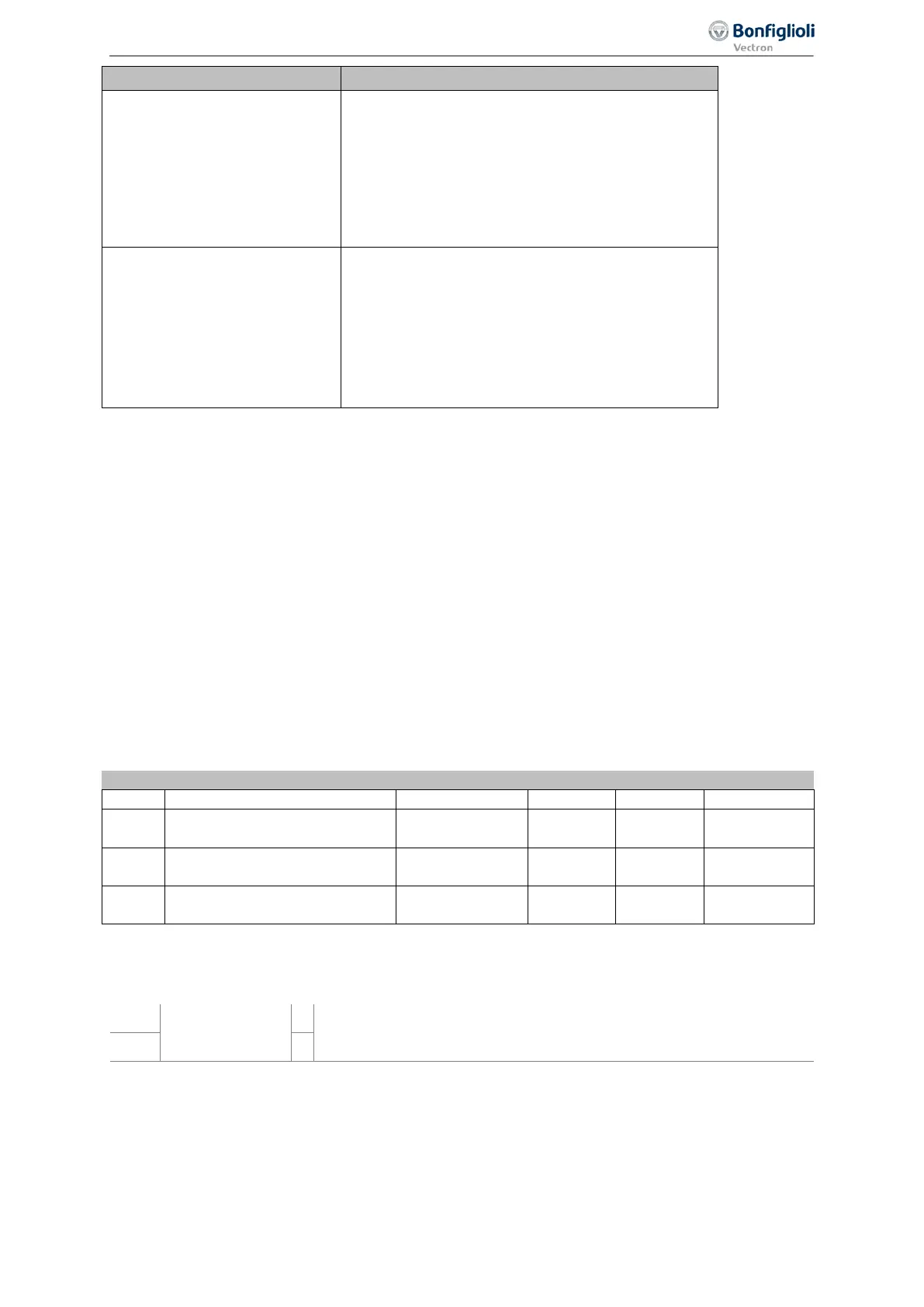
Output signals
Digital signals signal that of the function " motor protection " has been triggered.
180 -
Warning motor
protection
1)
Triggering of the function " motor protection " according to Operation
Mode
571 is signaled.
14 -
2)
1)
For linking to frequency inverter functions
2)
For output via a digital output. Select the signal source for one of the parameters 531, 532, 533,
554. See chapter 7.6.5 "Digital outputs".
249
Special functions 06/2013 Operating Instructions
Agile

 Loading...


