30 A. Use an AWG #10 maximum wire gauge on the 30 A circuit. The maximum branch circuit for the –48
VDC power supply module must not exceed 30 A.
The Cisco ASR 1002 Router has two of the same type power supplies in power supply slot 0 and power supply
slot 1. The power supply slot numbers are on the left side of the chassis and the power supplies are located
on the floor of the chassis. The power supply switch is a standby switch and is not considered a disconnect.
The –48 VDC input connector is a Euro-style terminal block. The largest size gauge of wire that the front
panel euro-terminal block can accept is AWG #10 wire. The terminal block is compliant with safety agencies’
guidelines and electrical requirements of the supply. Use the tie wraps to dress the input cable wires; there
are two tie wrap tabs on the –48 VDC power supply.
The –48 VDC power supply unit is secured into the system chassis with two captive screws mounted on the
faceplate.
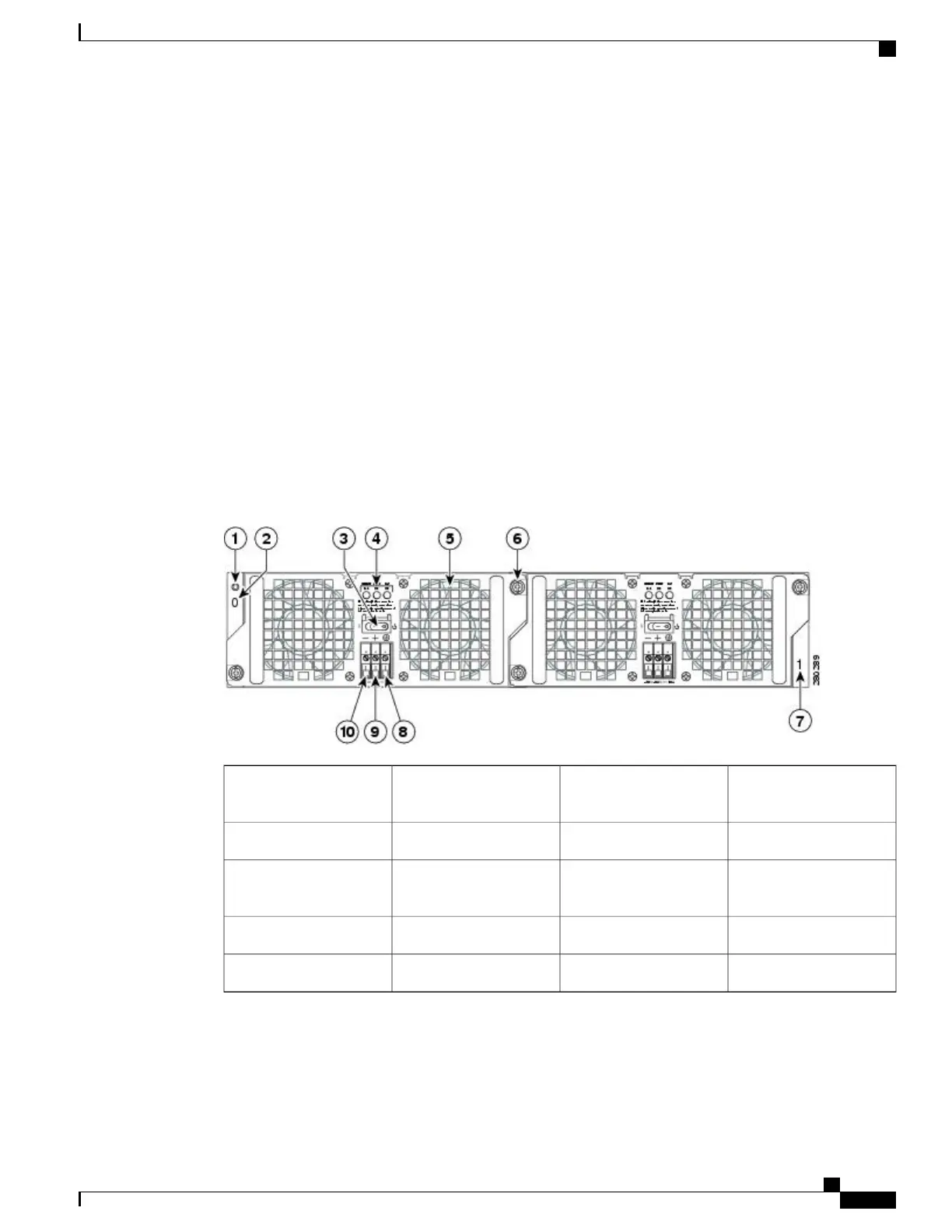
Cisco ASR 1002 Router –48 VDC Power Supply LEDs and Connector
The following figure shows the –48 VDC power supplies at the rear of the Cisco ASR 1002 Router. The Cisco
ASR 1002 Router supports up to two power supplies.
Figure 17: Cisco ASR 1002 Router
–
48 VDC Power Supply
Power supply captive
installation screw
6Chassis ESD socket1
Power supply slot 1 label7Power supply slot 0 label2
Ground lead8Power supply switch
standby/On (|)
3
Positive lead9Power supply LEDs4
Negative lead10Fan5
The following table describes the power supply LEDs and connectors on the rear of the chassis.
Cisco ASR 1000 Series Router Hardware Installation Guide
69
Cisco ASR 1000 Series Routers Component Overview
Cisco ASR 1002 Router –48 VDC Power Supply

 Loading...


