The +24 VDC power supply uses a spring-loaded terminal block. The input terminal block requires maximum
8AWG multi-strand wiring to support input current. The terminal block is compliant with safety agencies’
guidelines and electrical requirements of the supply. Use the tie wraps to dress the input cable wires; there
are two tie wrap tabs on the +24 VDC power supply. The +24 VDC power supply unit is secured into the
system chassis with two captive screws mounted on the faceplate.
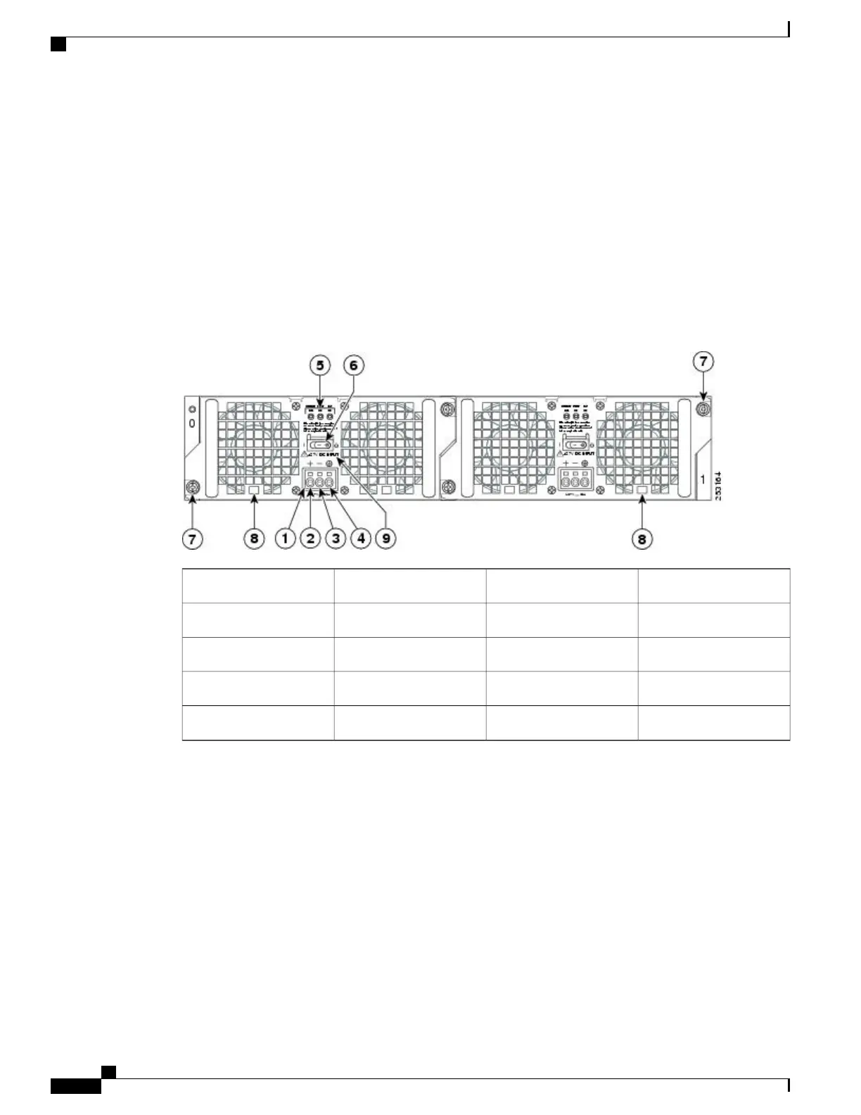
Cisco ASR 1002 Router +24 VDC Power Supply LEDs and Connector
The following figure shows the +24 VDC power supplies at the rear of the Cisco ASR 1002 Router. The Cisco
ASR 1002 Router supports two +24 VDC power supplies.
Figure 18: Cisco ASR 1002 Router Rear View With +24 VDC Power Supply
Standby/On switch6+24 VDC terminal block1
Captive fastener7Positive (+) lead2
Power supply tabs8Negative (-) lead3
+27 VDC INPUT label9Ground (GND) lead4
——
Power supply LEDs5
Cisco ASR 1000 Series Router Hardware Installation Guide
72
Cisco ASR 1000 Series Routers Component Overview
Cisco ASR 1002 Router +24 VDC Power Supply

 Loading...


