common input ranges for reference only. The –48 VDC power input connector is a Euro-style terminal block
that accepts three wires, one positive, one negative, and one grounding wire.
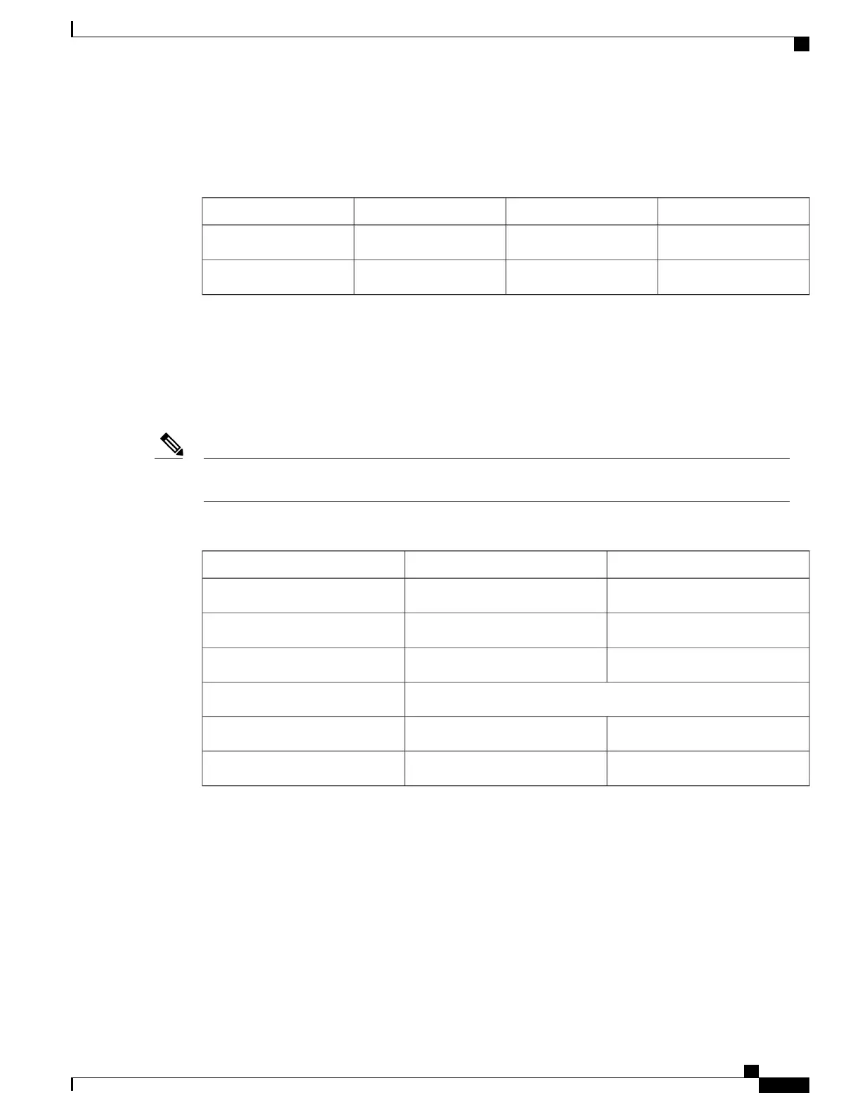
Table 27: Cisco ASR 1002 Router
–
48 VDC Power System Input
MaximumNominalMinimumVoltage Range (VDC)
–56–48–40.5
Domestic
–72–60–55
International
–48 VDC Power System Output for Cisco ASR 1002 Router
The –48 VDC power supply output tolerance is defined in the following table under all combinations of –48
VDC input line variation. Total system power consumption should not exceed 470 watts or output rating of
each power supply.
Two power supplies are used for redundant operation. System total power consumption shall never exceed
rating of one power supply to maintain redundancy.
Note
Table 28: Cisco ASR 1002 Router
–
48 VDC Power System Output Voltage and Current
+3.3 V+12 VDCOutput Voltage
–3.20 VDC–11.80 VDC
Minimum
–3.30 VDC–12.00 VDC
Nominal
–3.40 VDC–12.20 VDC
Maximum
Output Current
–0.10 A–2.0 A
Minimum
–3.125 A–39 A
Maximum
Cisco ASR 1002 Router +24 VDC Power Supply
This section provides information about the +24 VDC power supplies on the rear of the Cisco ASR 1002
Router. The recommended branch circuit breaker for the Cisco ASR 1002 Router +24 VDC power supply is
a 40 A UL listed circuit breaker.
The Cisco ASR 1002 Router has two of the same type power supplies in power supply slot 0 and power supply
slot 1. The power supply slot identifiers are zero (0) on the left side of the chassis rear and one (1) on the right
side of the chassis rear. The power supply switch is a standby switch and is not considered a disconnect.
Cisco ASR 1000 Series Router Hardware Installation Guide
71
Cisco ASR 1000 Series Routers Component Overview
Cisco ASR 1002 Router +24 VDC Power Supply

 Loading...


