ASR 1000 Series SIP slot
2
7Slot F0 with ASR 1000
Series ESP
3
Slot F1 with ASR 1000
Series ESP
4
Rear View
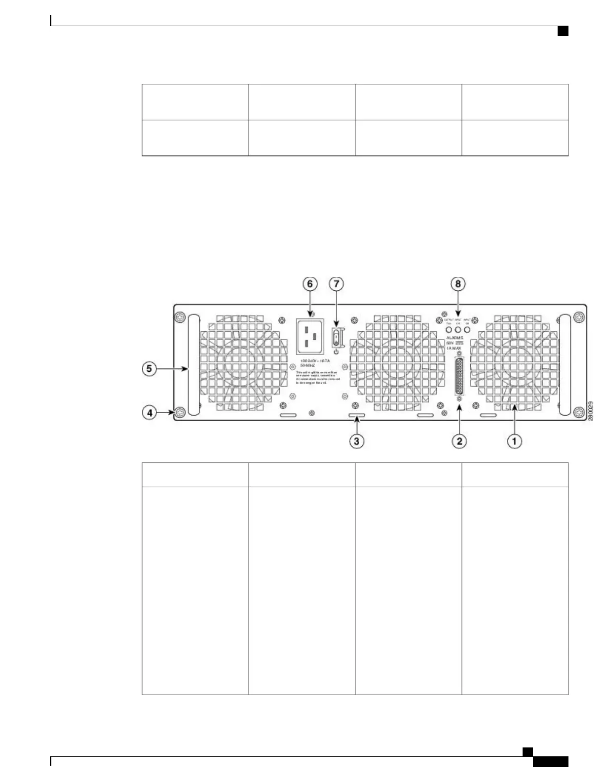
The following image shows the rear of the Cisco ASR 1006 Router with the ASR1006-PWR-AC power supply
installed.
Figure 35: Cisco ASR 1006 Router Rear View with the AC Power Supply (ASR1006-PWR-AC)
AC power supply handle5AC power supply fan1
AC power inlet6AC power supply DB-25
alarm connector—A
female DB-25 sub
connector which enables
you to attach an external
alarm monitoring facility
to the router, thus
supporting a telco-style of
handling alarm conditions
in the router.
For a description of the
DB-25 alarm connector,
see the “How Cisco
ASR1000-RP Alarm
Monitoring Works”
section on page 2-22 .
2
Cisco ASR 1000 Series Router Hardware Installation Guide
141
Cisco ASR 1006 Router Overview and Installation
Rear View
 Loading...


