STAT—status LED
8
USB port— one USB
high-speed (480Mbps)
port used for secure key
storage, storing of VPN
credentials, or bulk flash
storage for image and
configuration backup
3
PWR—Power LED
9USB LED4
——
LINK LED indicates
MGMT Ethernet port
activity
5
For detailed descriptions of the SPAs on which some of the IDCs are based, go to: http://www.cisco.com/
en/US/products/ps6267/products_data_sheets_list.html
Note
There are two field-replaceable units in the Cisco ASR 1001 chassis. They are the DIMMs and eUSB. In
order to service the components in the chassis, you must remove the power supplies and the chassis cover.
For instructions, see the “Removing and Replacing the Cisco ASR 1001 Router DIMM Memory Modules”
and the “Remove and Replace the eUSB Device on the Cisco ASR 1001 Router” sections in the Removing
and Replacing FRUs from the Cisco ASR 1000 Series Routers chapter.
Note
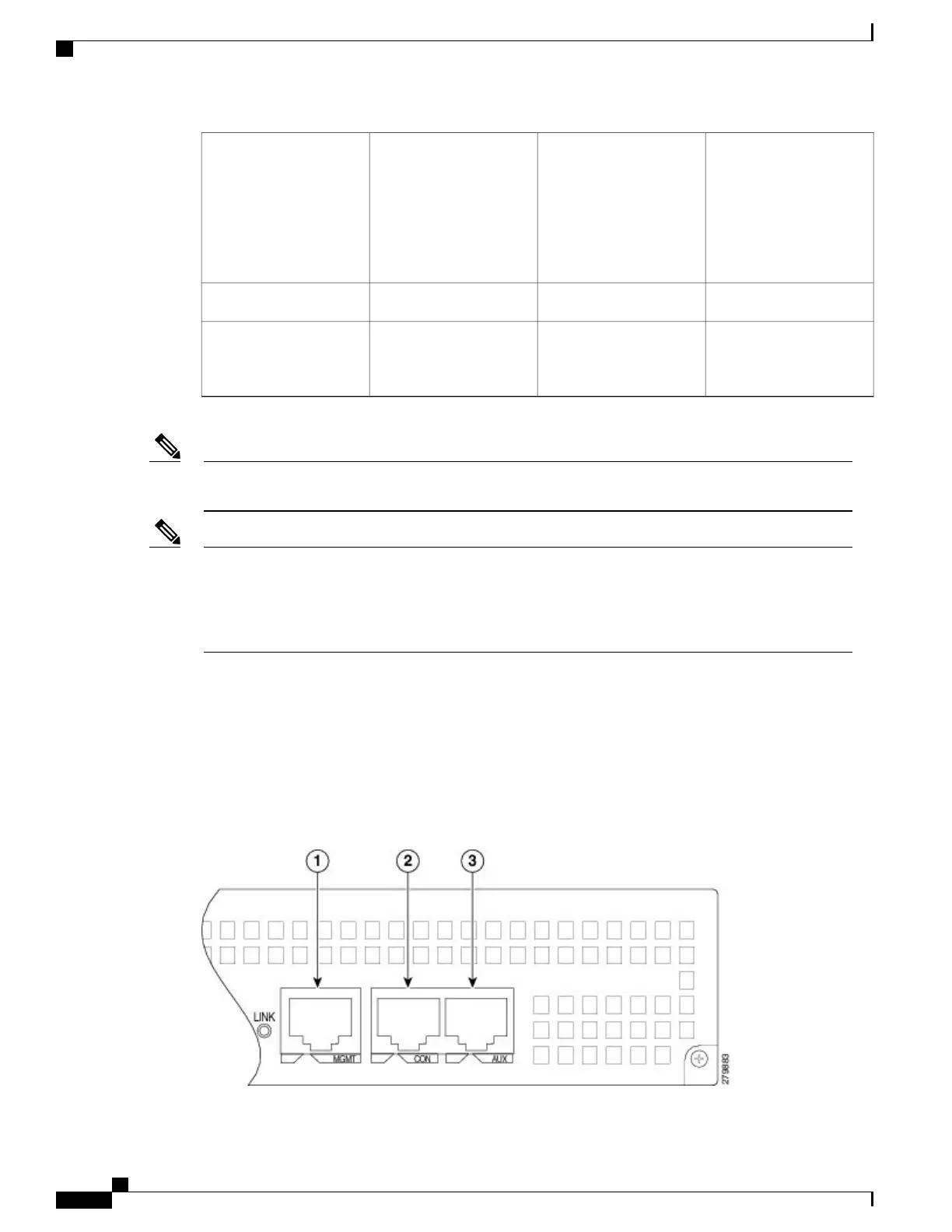
Cisco ASR 1001 Router Faceplate Common Components
The Cisco ASR 1001 Router RP faceplate has common components for each type of ASR 1001 Router
configuration. The preceding image and the following image show the Cisco ASR1000-RP faceplate with
LEDs and connectors for all configurations of the Cisco ASR 1001 Router.
Figure 202: Common Connectors for Cisco ASR 1001 Route Processor
Cisco ASR 1000 Series Router Hardware Installation Guide
416
Cisco ASR 1001 Router Overview and Installation
Cisco ASR 1001 Router Faceplate Common Components

 Loading...


