DETAILED STEPS
Step 1
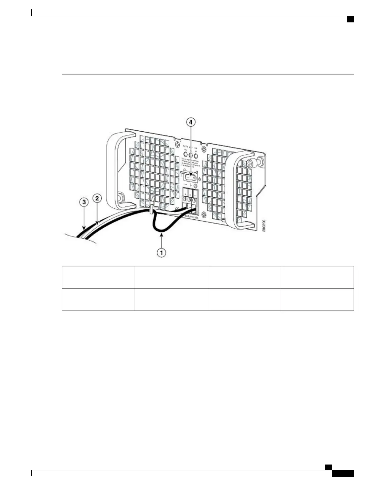
At the rear of the router, check that the power supply Standby switch is in the Standby position (see the following image
).
Figure 142: Cisco ASR 1002-F Router DC Power Supply Terminal Block Cable Connections
Negative lead wire3Ground lead with service
loop and cable tie
1
DC power supply Standby
switch
4Positive lead wire2
Step 2
Ensure that the negative and positive leads are disconnected from the site power source.
Step 3
Using a wire stripper, strip approximately 0.55 inch (14 mm) from the negative, positive, and ground leads.
Step 4
Insert the stripped end of the ground lead all the way into the ground lead receptacle on the DC input power supply, and
tighten the receptacle screw using a 3.5 mm flat-blade screwdriver to a torque of 0.5 to 0.6Nm.
Step 5
Insert the stripped end of the positive lead all the way into the positive lead receptacle and tighten the receptacle screw
using the same 3.5 mm flat-blade screwdriver. Repeat this step for the negative lead.
Make sure the entire stripped end of each lead is inserted all the way into its receptacle. If any exposed wire at
the stripped end of a lead is visible after inserting the lead into its receptacle, remove the lead from the receptacle,
use the wire stripper to cut the stripped end of the lead, and repeat Step 3 through Step 5.
Note
Four power supplies must be installed in the chassis at all times, with a minimum of two power supplies (one
per zone) connected to the mains in order to power on the system and ensure sufficient cooling. The system
fans are inside the power supply units and must spin for cooling. Because all the system fans can be powered
by one power supply, the second power supply unit does not have to be powered on, but must be connected.
Note
Cisco ASR 1000 Series Router Hardware Installation Guide
313
Cisco ASR 1002-F Router Overview and Installation
Connecting DC Input Power to the Cisco ASR 1002-F Router

 Loading...


