DETAILED STEPS
Step 1
At the rear of the chassis, check that the power switch on the power supply is in the Standby position.
Step 2
Plug the power cable into the inlet.
For additional AC power cable strain relief, secure the cable to the power supply handle by inserting a nylon
cable tie through the hole in the handle and around the cable.
Note
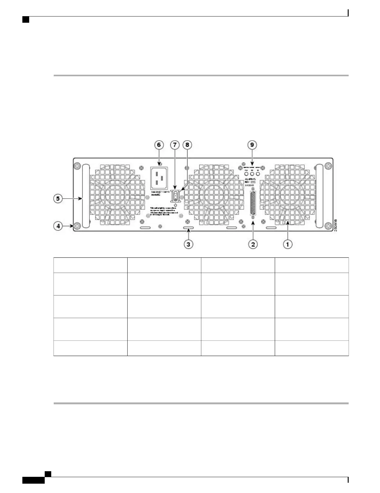
The following image shows the Cisco ASR 1013 Router AC power supply.
Figure 189: Cisco ASR 1013 Router AC Power Supply
AC power inlet6AC power supply fan1
AC power supply Standby
switch
7DB-25 alarm connector2
Protective shielding on both
sides of the Standby switch
8Tie-wrap tab3
AC power supply LEDs9AC power supply captive
screw
4
——
AC power supply handle5
Shielded cables must be used to connect to the DB-25 alarm connector on both the AC and DC power supplies
in order to comply with FCC/EN55022/CISPR22 Class A emissions requirements. See the “How Cisco
ASR1000-RP Alarm Monitoring Works” section on page 2-22 .
Note
Step 3
Plug the AC power supply cable into the AC power source.
What to Do Next
This completes the procedure for connecting AC-input power.
Cisco ASR 1000 Series Router Hardware Installation Guide
396
Cisco ASR 1013 Router Overview and Installation
Connecting AC Input Power to Cisco ASR 1013 Router

 Loading...


