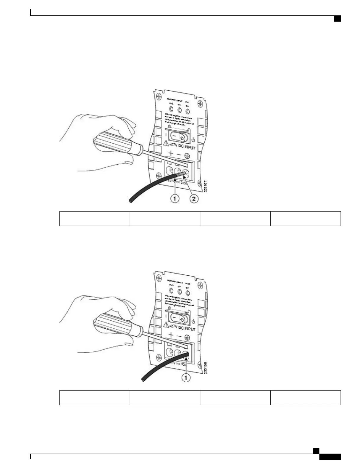
The following figure shows the +24 VDC power supply lead wire inserted into the terminal block.
Figure 288: Cisco ASR 1002 Router +24 VDC Power Supply Lead Wire Inserted into the Terminal Block
Copper wire2Lead wire insulation1
Step 8
Make certain no copper wire is visible as shown in the following figure which shows the lead wire fully inserted.
Figure 289: Cisco ASR 1002 Router +24 VDC Power Supply Lead Wire Fully Inserted
——
Fully-inserted lead wire1
Cisco ASR 1000 Series Router Hardware Installation Guide
583
Removing and Replacing FRUs from the Cisco ASR 1000 Series Routers
Removing and Replacing a +24 VDC Power Supply in Cisco ASR 1002 Router

 Loading...


