4. I/O Check Field Service Ver. 1.0 Aug. 2005
8
Duplex Unit/
Switchback Unit
Adjustment / Setting
4. I/O Check
4.1 Check procedure
• To allow sensors to be checked for operation easily and safely, data applied to the IC on
the board can be checked on the panel with the main unit in the standby state (including
a misfeed, malfunction, and closure failure condition).
<Procedure>
1. Call the Tech. Rep. Mode to the screen.
☞ For details of how to display the Tech. Rep. Mode screen, see the Adjustment/Setting
of the main unit service manual.
2. Touch the [I/O Check].
3. Touch the [Printer].
4. Touch the [Bypass/Duplex].
4.2 I/O check list
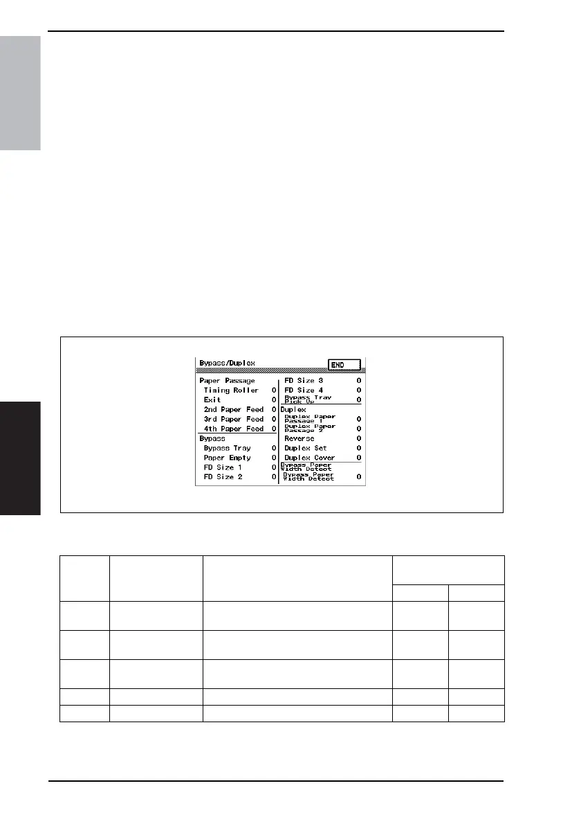
4.2.1 I/O check screen
• This is only typical screen which may be different from what are shown on each individ-
ual main unit.
4.2.2 I/O check list
4040F3E566DA
Symbol Panel display Part/Signal name
Operation characteris-
tics/Panel display
10
PC24
Duplex Paper
Passage 1
Duplex Unit Upper Transport Sensor
Paper
present
Paper not
present
PC25
Duplex Paper
Passage 2
Duplex Unit Lower Transport Sensor
Paper
present
Paper not
present
PC26 Revers Switch Back Unit Sensor
Paper
present
Paper not
present
- Duplex Set Duplex Unit Set signal Not set Set
PC23 Duplex Cover Duplex Unit Door Sensor Open Close