10. Malfunction code Field Service Ver. 1.0 Aug. 2005
42
FS-508/PU-501/OT-601
Troubleshooting
10.2 Solution
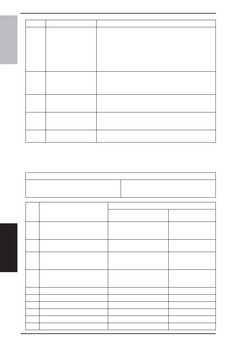
10.2.1 C1183: Elevator Motor Ascent/Descent Drive Failure
C11A3 Shutter Drive Failure
• The Shutter Home Position Sensor (PC16-FN) is not
unblocked even after the set period of time has elapsed after
the Exit Open/Close Motor (M6-FN) is energized (beginning
of shutter-opening operation).
• The Shutter Home Position Sensor (PC16-FN) is not blocked
even after the set period of time has elapsed after the Exit
Open/Close Motor (M6-FN) is energized (beginning of shut-
ter-closing operation).
C11B0
Staple Unit CD Drive
Failure
The Staple Home Position Sensor (PC10-FN) is not blocked
even after the set period of time has elapsed after the Stapling
Unit Moving Motor (M7-FN) is energized (beginning of return
operation to predetermined position).
C11B2 Staple Drive Failure
The Home Position Sensor is not blocked even after the set
period of time has elapsed after the Staple Motor is energized
(beginning of staple operation).
C11C0
Punch Cam Motor Unit
Failure
The Punch Motor Pulse Sensor cannot detect both edges of H/L
even after the set period of time has elapsed while the Punch
Drive Motor is energized.
CC155
Finishing Option Flash
ROM Failure
• Data of flash ROM of the finishing options is determined to be
faulty when the power is turned ON.
Code Description Detection Timing
Relevant Electrical Parts
Elevator Motor (M11-FN)
Elevator Tray Home Position Sensor (PC3-FN)
Elevator Tray Lower Limit Sensor (PC14-FN)
Top Face Detection Sensor (PC15-FN)
Elevator Board (PWB-B FN)
Main Control Board (PWB-A FN)
Step Action
WIRING DIAGRAM
Control Signal
Location
(Electrical Component)
1
Check the M11-FN connector for
proper connection and correct as
necessary.
--
2
Check M11-FN for proper drive cou-
pling and correct as necessary.
--
3
If OT-601 is connected, check the
connector for proper connection,
and correct as necessary.
--
4
Check the installation position of the
OT-601 tray, and correct as neces-
sary.
--
5 M11-FN operation check PWB-A FN PJ7A FN-1 to 2 FS-508 G-7
6 PC3-FN I/O check PWB-A FN PJ12A FN-2 (ON) FS-508 G-4
7 PC14-FN I/O check PWB-B FN PJ2B FN-3 (ON) FS-508 H-6
8 PC15-FN I/O check PWB-B FN PJ2B FN-6 (ON) FS-508 H-6
9 Change PWB-B FN - -
10 Change PWB-A FN - -