4. Sensor Check Field Service Ver. 1.0 Aug. 2005
6
JS-502
Adjustment / Setting
4. Sensor Check
4.1 Check procedure
• To allow sensors to be checked for operation easily and safely, data applied to the IC on
the board can be checked on the panel with the main unit in the standby state (including
a misfeed, malfunction, and closure failure condition).
<Procedure>
1. Display the Tech. Rep. Mode screen.
☞ For details of how to display the Tech. Rep. Mode screen, see the Adjustment/Setting
of the main unit service manual.
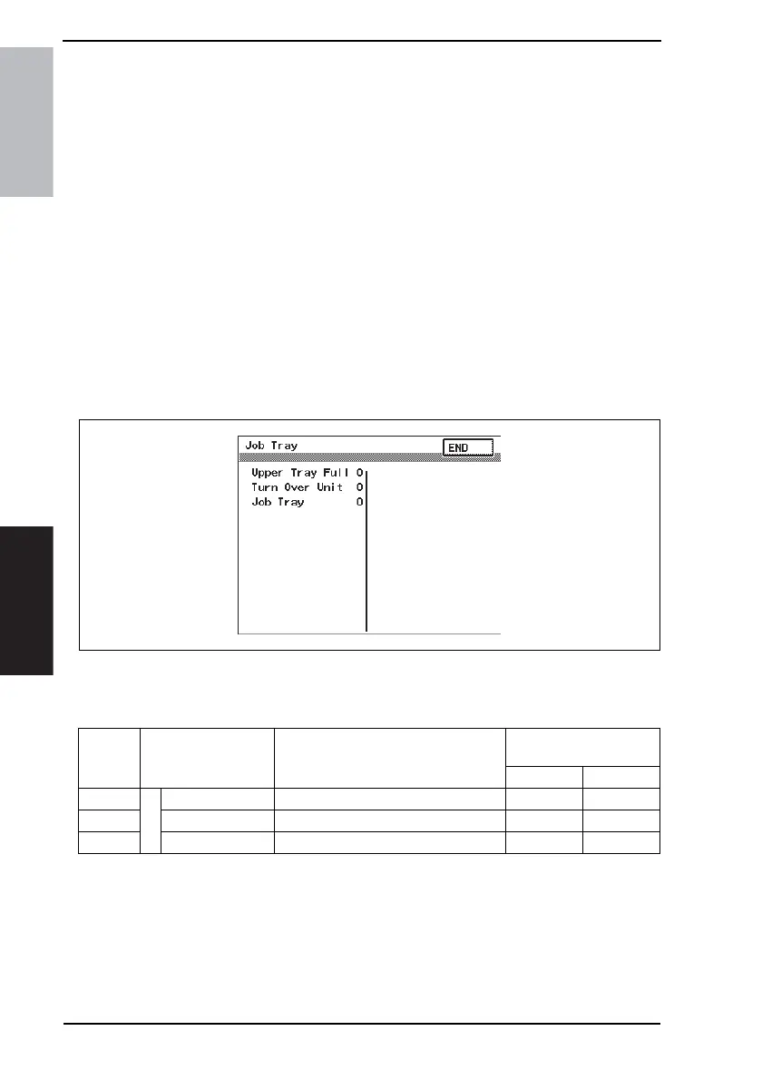
2. Touch [I/O Check].
3. Touch [Job Tray].
4.2 I/O check list
4.2.1 I/O check screen
• This is only typical screen which may be different from what are shown on each individ-
ual main unit.
4.2.2 I/O check list
A. Job Tray
4347F3E501DA
Symbol Panel display Part/Signal name
Operation characteristics/
Panel display
10
PC1-JOB
Job Tray
Upper Tray Full Paper Full Detection Sensor Blocked Unblocked
- Turn Over Unit Turn Over Unit Set signal Set Not set
- Job Tray Job Tray Set signal Set Not set