10. Malfunction code Field Service Ver. 1.0 Aug. 2005
46
FS-508/PU-501/OT-601
Troubleshooting
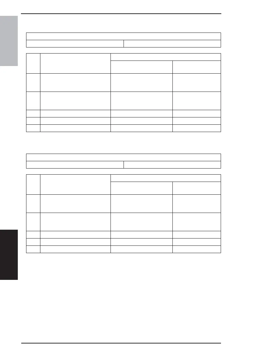
10.2.8 C11B2: Staple Drive Failure
10.2.9 C11C0: Punch Cam Motor Unit Failure
Relevant Electrical Parts
Staple Unit Main Control Board (PWB-A FN)
Step Action
WIRING DIAGRAM
Control Signal
Location
(Electrical Component)
1
Check the Staple unit connector for
proper connection and correct as
necessary.
--
2
Check the Staple Unit for proper
drive coupling, and correct as nec-
essary.
--
3 Staple Unit operation check - -
4 Change Staple Unit - -
5 Change PWB-A FN - -
Relevant Electrical Parts
Punch Unit Main Control Board (PWB-A FN)
Step Action
WIRING DIAGRAM
Control Signal
Location
(Electrical Component)
1
Check the Punch Unit connectors
for proper connection, and correct
as necessary.
--
2
Check the Punch Unit for proper
drive coupling, and correct as nec-
essary.
--
3 Punch Unit I/O check - -
4 Change Punch Unit - -
5 Change PWB-A FN - -