Field Service Ver. 1.0 Aug. 2005 8. Trouble code
33
PC-402
Troubleshooting
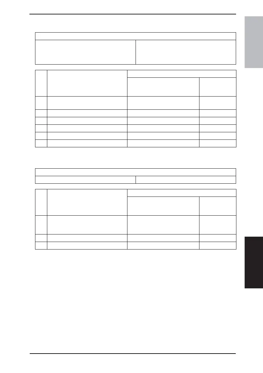
8.3.3 C0210: LCT Lift Failure
8.3.4 C0212: LCT Lock Release Failure
Relevant electrical parts
Tray Upper Limit Sensor (PC4-LCT)
Tray Lower Position Sensor (PC13-LCT)
Elevator Motor Pulse Sensor (PC10-LCT)
Lower Limit Sensor (PC7-LCT)
Main Control Board (PWB-C1 LCT)
Step Action
WIRING DIAGRAM
Control signal
Location
(Electrical com-
ponents)
1
Check the sensor connectors for proper
connection, and correct as necessary.
--
2 PC4-LCT sensor check PWB-C1 LCT PJ5C1 LCT-12 (ON) PC-402 C-7
3 PC13-LCT sensor check PWB-C1 LCT PJ2H<A> LCT-9 (ON) PC-402 G-3
4 PC10-LCT sensor check PWB-C1 LCT PJ2H<A> LCT-5 (ON) PC-402 G-5
5 PC7-LCT sensor check PWB-C1 LCT PJ2H<A> LCT-2 (ON) PC-402 G-6
6 PWB-C1 LCT replacement - -
Relevant electrical parts
Tray Lock Solenoid (SL1-LCT) Main Control Board (PWB-C1 LCT)
Step Action
WIRING DIAGRAM
Control signal
Location
(Electrical com-
ponents)
1
Check the SL1-LCT connector for
proper connection, and correct as nec-
essary.
--
2 SL1-LCT operation check PWB-C1 LCT PJ7C1 LCT-4 (ON) PC-402 C-8
3 PWB-C1 LCT replacement - -