AS Autosampler Operator’s Manual
140 Doc. 065051-03 1/08
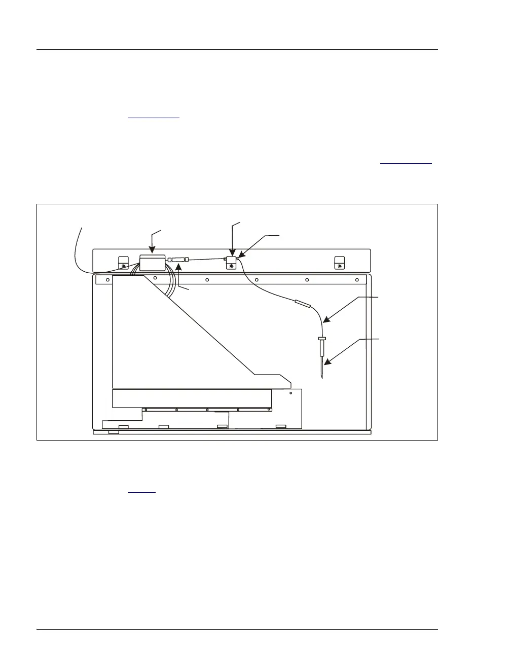
6. The sampling needle line is coiled and held by a bracket and clamp on
the upper-right side of the autosampler compartment (see
Figure 5-11
). To remove the tubing, use a flathead screwdriver to
gently pry the center bracket apart. Then, lift the tubing out of the
bracket and clamp.
7. Measure the distance from the second yellow sleeve (see Figure 5-11
)
to the needle. When installing the new sampling needle assembly,
position the sleeve on the new line the same distance from the needle.
Figure 5-11. Sampling Needle Line Bracket and Clamp (Right Side of Compartment)
8. If you are replacing an 8.5 mL assembly (P/N 061267), go on to
Step 9
. If you are replacing a 1.2 mL sampling needle assembly
(P/N 054271), follow the steps below to disconnect the sampling
needle line:
a. Disconnect the sampling needle assembly from port C on the
sample syringe valve.
b. Pull the ferrule fitting off the end of the tubing and remove the
bolt.
Bracket
Clamp
To Port
on
ample
Syringe Valve
Coupler
Samplin
Needle
Line
Second Yellow Sleeve
Note: This coupler is
included only on the 8.2 mL
sampling needle assembly.
Samplin
Needle