GENERAL
. m•
....
================================~rF
ENGINE
750
s.s
. 900
s.s
.
Twin
-c
ylinder,
90
° l lype con
fi
gurolion, 4·s
tr
ok
e.
Bore in. ·.. .. .. .. .. .. .. .. .. .. ..
..
.. ..
.. .. .. ..
.. .. .. ..
..
. . . 3. 4
64
5 3 . 6 2
20
Stroke
in
................................................
2.
4212
2.6771
Total disploment
cu
.
in
.....
...
............
...........
45.63
55.14
Compression ratio
..
. ........... ... ..... .... I :9±0.5 I :9,
2±0
,5
M ax.
po
wer (at the wheel)
kW
[
HP)
...
.. .
..
£14
.1 [601
56
.3 (731
at r
pm
... .............
..........
..... .. 8.
50
0 7 .
000
Max
. engine speed
................................
9.000
IMPORTANT
· Under no circumstances
th
e engine
must
goes over
9000
rpm.
TIMING
SYSTEM
•DE
SMODROMIC •
tim
ing
system,
two va
lves
each cylinder, controlled
by
four
rocker arms (two opening and two closing rocker
arms)
and
by
four lobes
O.H
.
C.
It is
co
n
tr
olled by the dri
vi
ng
shaft
th
ro
ugh
cy
lindrical gears, p
ull
e
ys
and toothed be
lt
s.
The
va
l
ve
opening and
cl
osi
ng diagr
am
is the
following.
Checking
data
with o clearance of:
in
. ........ 0 .
008
0 .
04
Inlet valve: diameter
in
...
........
........
..
........ 1
.6
14
1.693
Op
ens before T.D.C. . .. ..... .
.. ..
...... ...
..
... 3 1°
20
°
Cl
oses
after B.D.C. .......
..
..........
..
........... 8
8°
60
°
Exhaust
valve: diamet
er
in.....
.........
........
.. 1.
378
1.496
Opens before B
.D
C...
..
.. .....................
72o
58°
Closes a her T. D.
C.
.
..
.. . . . . . .. . .. .. .
..
. .. .. . .. . .. .
46°
20°
O
pe
ra
tion cl
ea
rance of val
ve
lapp
ets,
wi
th
co
ld engin
e,
mu
st b
e:
Op
ening rocker arm:
0 .
0031
+0
.
0039
in
. (Inlet)
0 .
0039
+0 .
0047
in. (
Exhaust
)
Closing rocker arm.
0+0
.
00078
in. (Inlet and Exh
aust
)
Lift:
(check
in
g doto with a clearance of 0 in
.)
Induction i
n.
.. . .. . .. . . .. . . . . .. ..
.. ..
.. .. .
..
.. . . . . ... .. 0 .
36
8 0.4
63
Exhaust
in
.....
..............................
..........
0.334 0.415
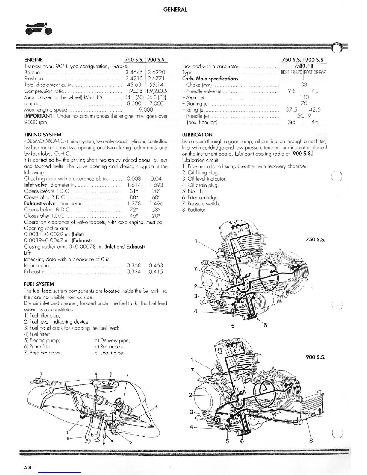
FUEL
SYSTEM
The fuel feed
sy
stem comp
on
e
nt
s ore located i
nsi
de t
he
f
uel
ton
k,
so
th
ey ore not visible from
ou
tsid
e.
Dry air inlet
ond
cleaner, located under
the
fuel
tonk.
Th
e
fuel
feed
system
is
so constituted.
l )
Fu
el filler c
op
:
2) Fuel level indicating device,
3)
Fu
el
hand cock
fo
r st
op
ping the
fuel
feed;
4)
Fuel
fille
r;
5) Electric pump; a) Delivery pipe;
6 )
Pu
mp fi
lt
er
b)
Ret
ur
n pipe;
7) B
re
a
th
er valve,
c) Drain p
ip
e.
A.8
750
S.S.)900
s.
~
Provided wi
th
a carbure
to
r: . . . . . .. .. . . . . . . .. M IKUN I
Type ....
..
.. ...................... ......
..........
.......
BDST
3B·B70
I
BDST
38·867
Carb. Main
specifications
I
- Choke
(m
m) ..
........
.....
...............
...
38
- N eedle valve j
et
.. ..
.. .. .. . . . . .. .. .. . .. . .. . . ..
Y-6
! Y· 2
-
Ma
in
j
et.
..
..
............. 1
40
-
Star
ting
jet
. .. . . .. .. . .. .. . . . . .. . .. .. .. . .. . .. .. .. .
70
- Idling
jet...........
..........
......... ... ...... .....
37
.5 I
42
.5
- Needle jet
..
.. ..
..
.. .. .. .. .. . .. . .. ..
..
. .. .. .. .. . ..
5C
19
{
pos.
fr
om
top) ........ ...
.........
.......... 3
rd
I 4th
LUBRICATION
By
pressure
thr
ough o gear pump, oil purification through o net filter,
filter
with cortdridge and
low
pr
essure
temperature indicator
pla
ced
on the instr
um
en
t board. Lubricant cooling ra
dia
tor (
900
S.S.)
Lu
b
ri
colion cir
cu
it:
1)
Pipe un
io
n for oil
sum
p breat
her
w
ith
recovery chamber
2)
Oil
filling plug.
3)
Oil
level indicator.
4)
Oi
l drain
pl
ug
.
5) N et
fi
lter.
6)
Filter cartridge.
7)
Pr
essur
e s
wi
tch.
8)
Rad
iator.
1
1
5
750 s.
s.
5
6
900
s.
s.
6
8
I
\
(
)
'
'
,.
'-..../