D
IRECTION FR091521, REVISION 1 VIVID S60N/VIVID S70N BASIC SERVICE MANUAL
8-114 Section 8-5 - Electronic Cage Components - Replacement Procedures
PRELIMINARY
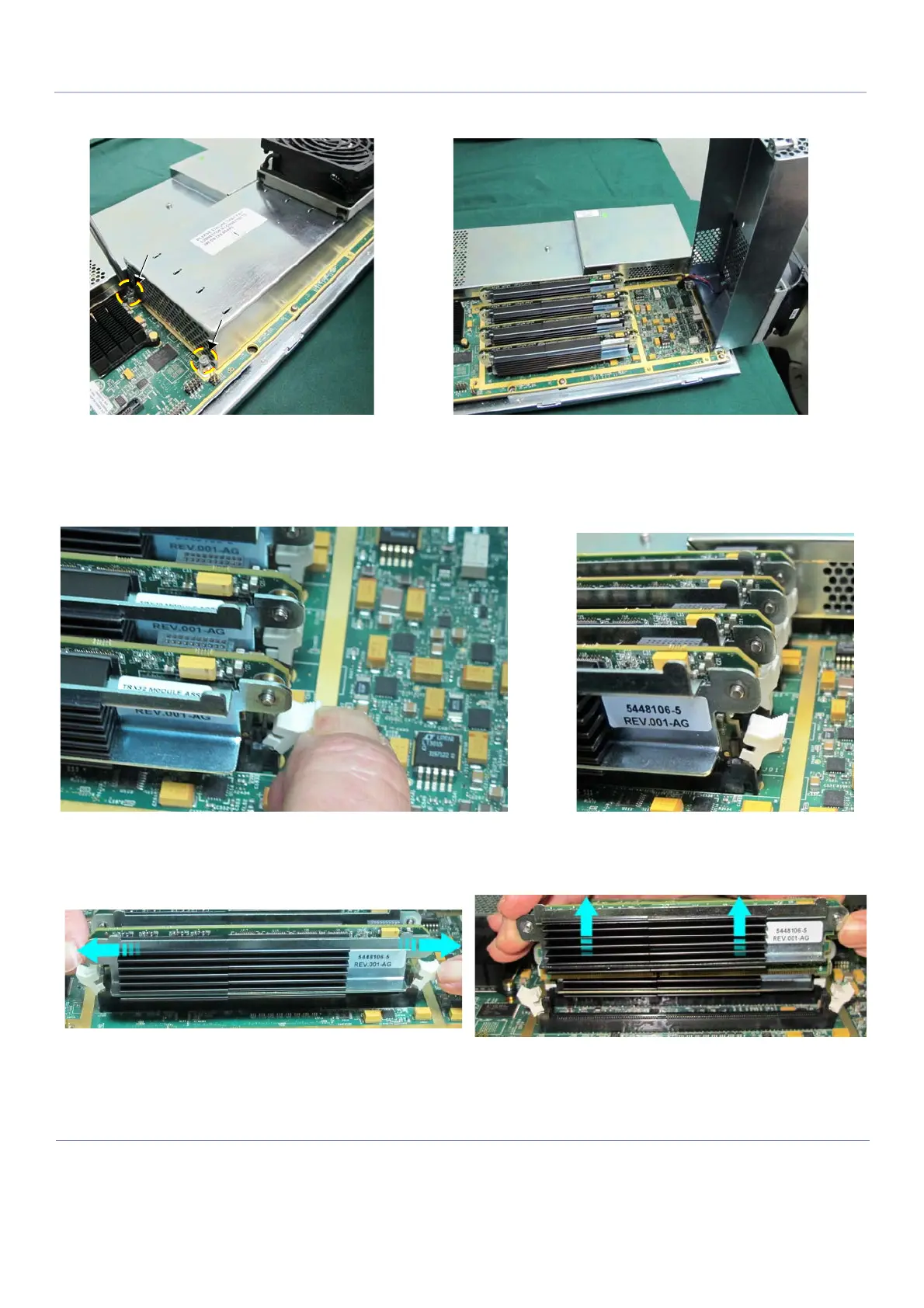
8) Loosen the 2 screws that secure the metal cover of the TRX32 Box; open the cover (Figure 8-138).
Note: The four TRX32 Boards are each secured in position on the CFE Board by way of a white
plastic holder at each end of the TRX32 Board. These are opened by gently pulling them
outwards to tilt the holder away from the edge of the Board, as shown in Figure 8-139.
9.) Open each white plastic holder located on either end of the first TRX32 Board to release the board,
then slide the Board upwards to remove it.
10.)Repeat step 9 to remove each of the remaining TRX32 Boards
NOTE: In the event that the replacement CFE Board is not been installed immediately, keep the four TRX32
Boards in a safe place as they will be required later for the installation procedure.
Figure 8-138 Opening the Metal Cover of the TRX32 Box
Figure 8-139 TRX32 Boards Secured with Plastic Holders
Figure 8-140 Removing a TRX32 Board

 Loading...


