Operation Manual – Multicast Protocol
Quidway S3900 Series Ethernet Switches-Release 1510 Chapter 2 IGMP Snooping Configuration
Huawei Technologies Proprietary
2-15
Table 2-14 Network devices and their configurations
Device Description
Switch A Layer 3 switch
The interface IP address of VLAN 20 is 168.10.1.1.
The Ethernet1/0/1 port is connected to the
workstation and belongs to VLAN 20.
VLAN 10 is the multicast VLAN.
Ethernet1/0/5 belongs to VLAN 2, Ethernet1/0/6
belongs to VLAN 3, and Ethernet1/0/10 is
connected to Switch B.
Switch B Layer 2 switch
VLAN 2 contains Ethernet1/0/1 and VLAN 3
contains Ethernet1/0/2. The two ports are
connected to PC1 and PC2 respectively.
Ethernet1/0/10 is connected to Switch A.
PC 1 User 1
PC1 is connected to the Ethernet1/0/1 port on
Switch B.
PC 2 User 2
PC2 is connected to the Ethernet1/0/2 port on
Switch B.
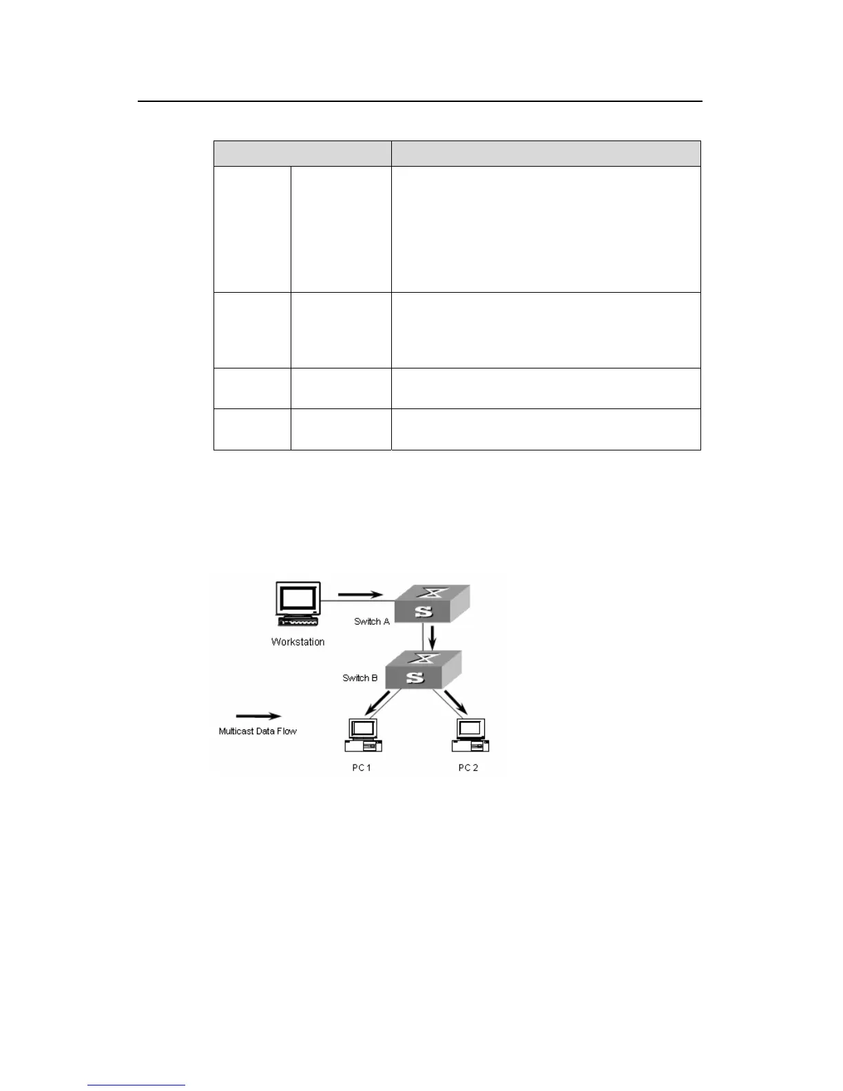
Configure a multicast VLAN, so that the users in VLAN 2 and VLAN 3 can receive
multicast streams through the multicast VLAN.
II. Network diagram
Figure 2-4 Network diagram for multicast VLAN configuration
III. Configuration procedure
The following configuration is based on the prerequisite that the devices are properly
connected and all the required IP addresses are already configured.
1) Configure Switch A:
# Set the interface IP address of VLAN 20 to 168.10.1.1 and enable the PIM DM
protocol on the VLAN interface.

 Loading...