Valve clearance adjustment
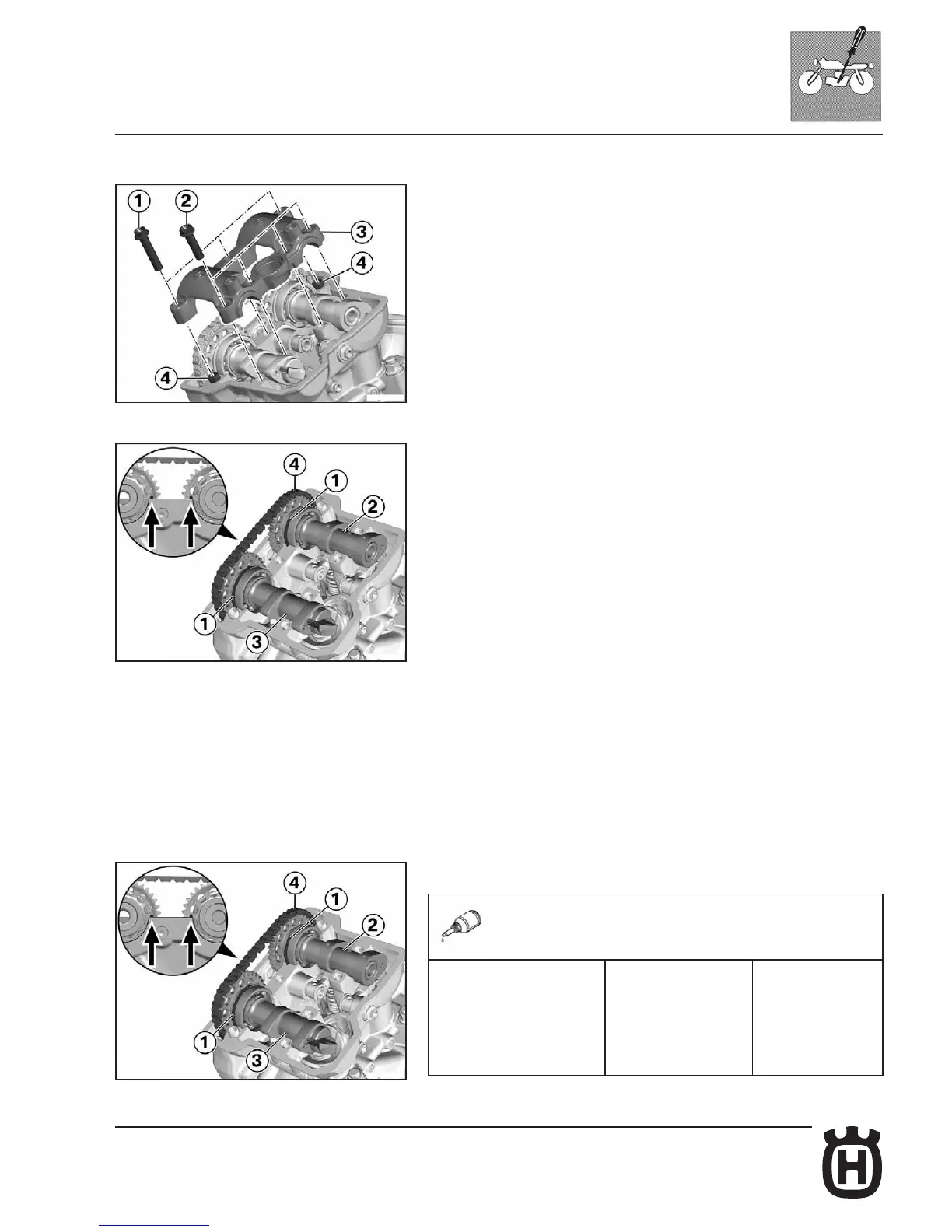
Bearing mount disassembly
• Remove screws (1, 2).
• Disassemble bearing mount (3).
• Remove guide sleeves (4).
Camshaft disassembly
• Take special care to camshaft position: both shaft gears reference marks (ar-
rows) shall be aligned with sealing surface.
• Remove intake (2) and exhaust (3) camshaft stop washers (1), and release
shafts with a suitable tool.
• Remove timing chain (4) at rst from intake shaft (2) sprocket, then from
exhaust shaft (3), and lay it in a safe position, to prevent it from falling to the
ground.
• Remove intake camshaft (2).
• Remove exhaust camshaft (3).
• Mark bucket-type tappet.
• Take out bucket-type tappets, overturn rocker arms.
• Before tting shims and new half-balls, measure the thickness using a mi-
crometer calliper.
• Replace shims and half-balls, making sure they are correctly positioned.
• Take rocker arms to basic position, and t bucket-type tappets by paying
special attention to the reference mark.
Camshaft assembly
• Make sure that crankshaft is well secured at TDC.
• Lubricate all bearing surfaces.
Consumables
Molykote D Paste Consumables
Clear solid lubricant for
metal part assembling
and settling
 Loading...