92
[Global Specification]
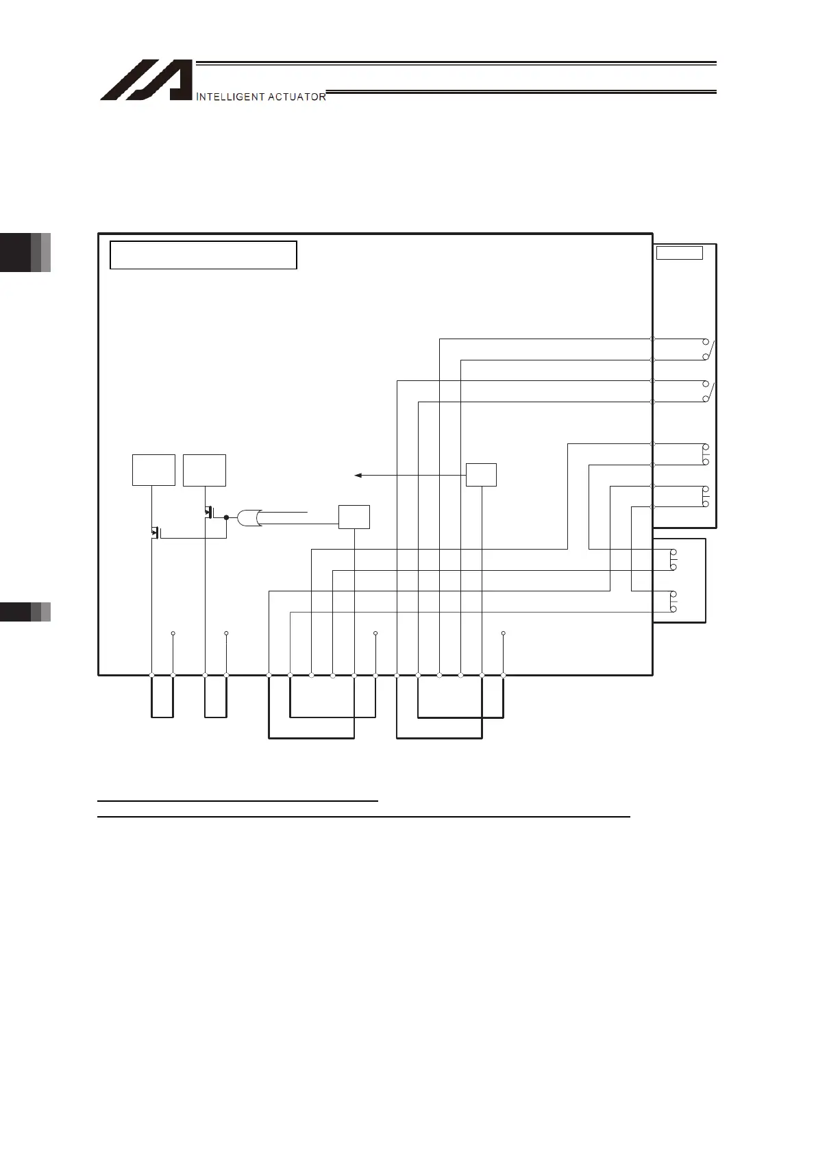
• All the motor drive power supply lines are cut off by FET.
•Because the emergency stop line on the connector for teaching and enable line are always activated,
motor drive becomes available by using a dummy plug (DP-2) when the connector for teaching is not
in use.
TP
9. EMGS 1-
10. EMGS 1+
7. EMGS 2-
8. EMGS 2+
12. EMGIN
3. ENBS 1-
4. ENBS 1+
1. ENBS 2-
2. ENBS 2+
6. ENBIN
11. EMGOUT
5. ENBOUT
VP24S VP24S
12.
EMGS1+_TP
13.
EMGS1- _TP
16.
EMGS2+_TP
24.
EMGS2- _TP
17.
ENBS 1+_TP
19.
ENBS 1- _TP
21.
ENBS 2+_TP
22.
ENBS 1- _TP
ENBOK
MPO
MPI
24 V
EMG SW
/ SDWN
MPO_B
MPI_B
24 V
3rd, 4th axis 1st, 2nd axis
Motor Drive
Circuit
Motor Drive
Circuit
EMG
Status
Detection
ENB
Status
Detection
Emergency Stop, Enable Internal Circuit and External Wiring at Delevery
* 24V DC/10mA or less for EMGIN and ENBIN
* Contact output (EMGS1+/-, EMGS2+/- and ENBS2+/-) should be 30V DC/0.5A or less.
TTA AC Servo Motor Type
Chapter 3 Wiring3.2 Power Supply, Emergency Stop Circuit and Enable Circuit

 Loading...