115
3.4 Wiring Method
3.4.1 Wiring on AC Inlet for Power Supply
Input power voltage range: 100 to 230V AC±10%
There are two types of power supply codes enclosed.
1) For 100V AC Use the enclosed cable with one end with inlet and the other with outlet.
2) For 200V AC Cable with one end with inlet and the other with ring-tongue terminals (3
terminals) or inlet side socket only
It is necessary to have an installation work to connect a power supply cable for 200V AC.
Make sure that a person with knowledge of electricity performs the wiring.
3.4.2 Wiring for the Teaching Tool
A teaching tool can be connected with RS232C or USB.
The teaching connector is used to connect an IAI teaching pendant or PC (PC software) so that the
equipment can be operated, set up or otherwise manipulated from the teaching pendant/PC.
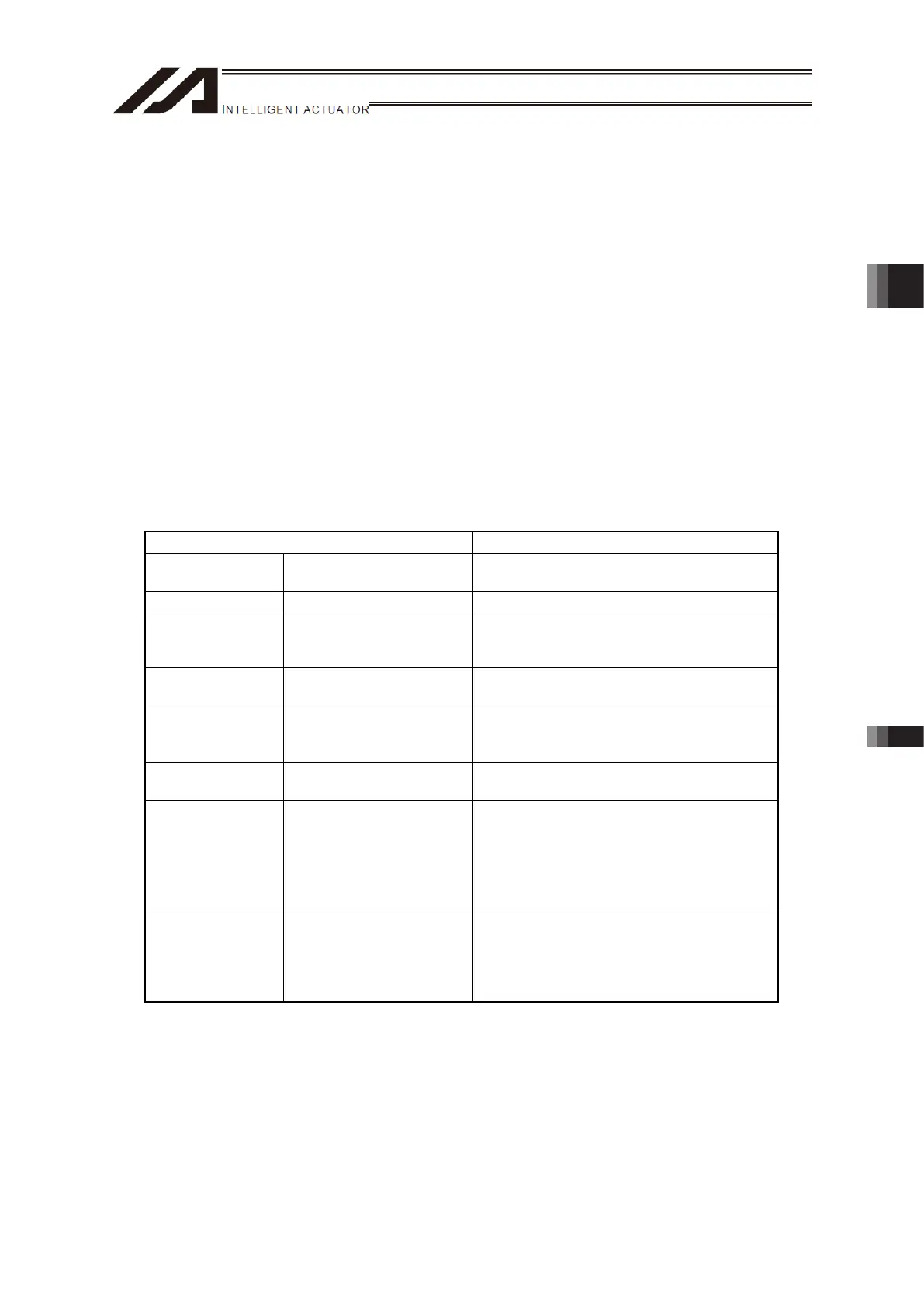
List of Teaching Connector Interface Specifications
Specification Remark
Connecter
RS232C (DSUB-25)
USB (Type B)
XM3B-2542-502L (by OMRON)
UBBS-4R-D14-4D (by JST)
Baud Rate 115.2 kbps max.
Maximum
Connection
Distance
10m (RS232C)
5m (USB)
At 38.4Kbps
Connected Unit PC or dedicated teaching
pendant
PC, teaching pendant
Power Supply
(RS232C)
5V DC or 24V DC Each line is fitted with multiple fuses to
protect against short circuit. (These fuses
trip at 1.1 to 2.2 A.)
Protocol Serial communication
protocol (Format B)
Emergency Stop
Control
(RS232C)
Emergency stop relay
drive (24-V drive)
A line for driving the emergency stop relay
is provided in the interface connector and
connected to other emergency stop
contacts in series. Two independent
emergency stop input circuits are installed
to provide redundancy.
Enable Control
(RS232C)
Enable switch line (24-V
drive)
An enable switch connection wire is
provided for interlock with operator’s
operations. Two independent enable input
circuits are installed to provide
redundancy.
Chapter 3 Wiring 3.4 Wiring Method

 Loading...