Chapter 7 Appendix7.1 Work and Tool Coordinate System Features for Linear Axis
246
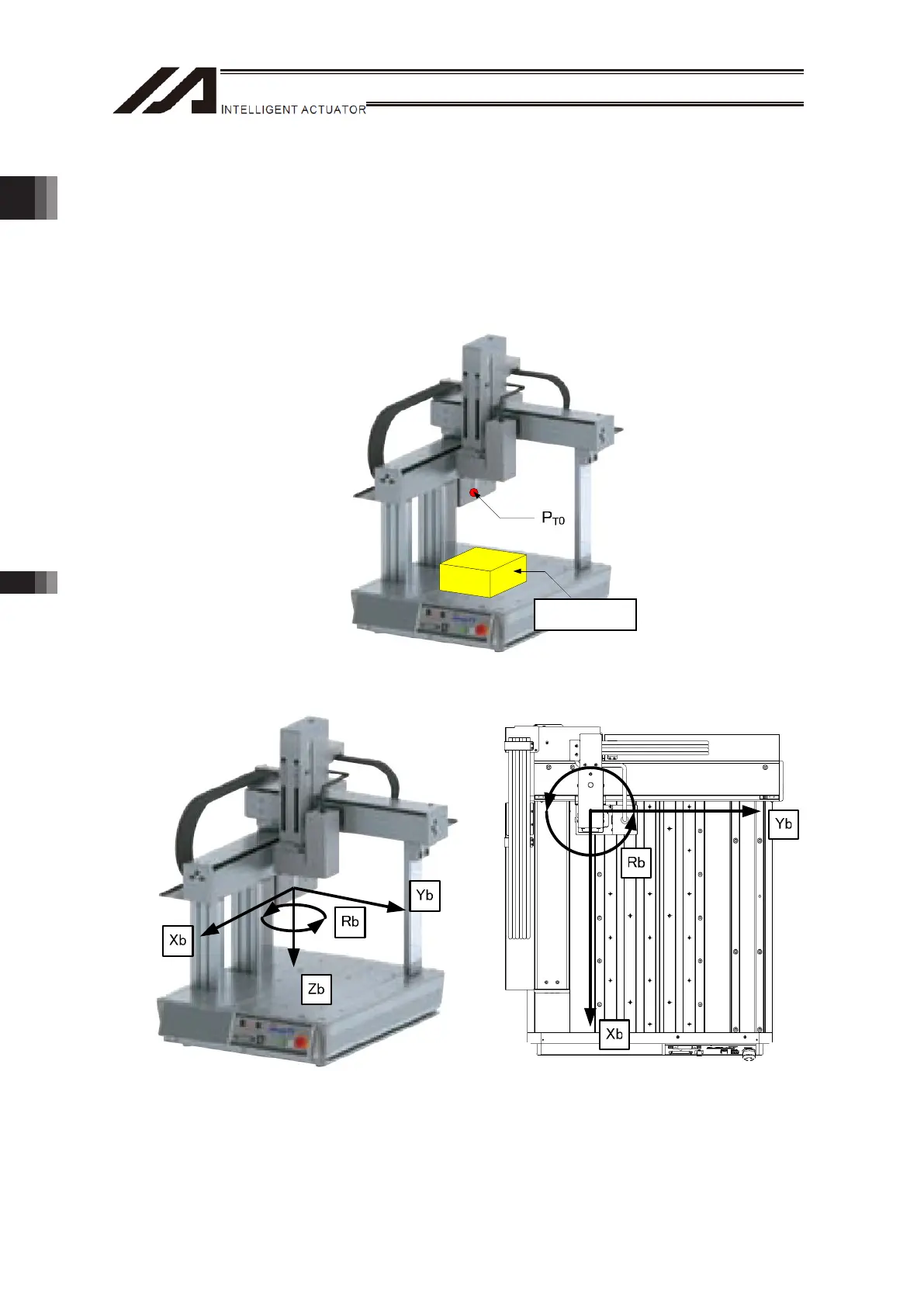
[2] Base Coordinate System
It is the coordinate system to indicate the position of the datum point for tool installation against the
work piece mount face. Work Coordinate System No. 0 (work coordinate system offset 0) = Base
Coordinate System. X axis of Base Coordinate System is described as Xb, Y axis as Yb, Z axis as
Zb and R axis as Rb.
(Example) TTA-C4 (XYZ Home Standard Specification)
The base coordinate system can be defined as shown below.
Work Piece

 Loading...