Chapter 9 External Dimensions9.1 Servo Motor Type, Pulse Motor Type (Battery-less Absolute Specication)
322
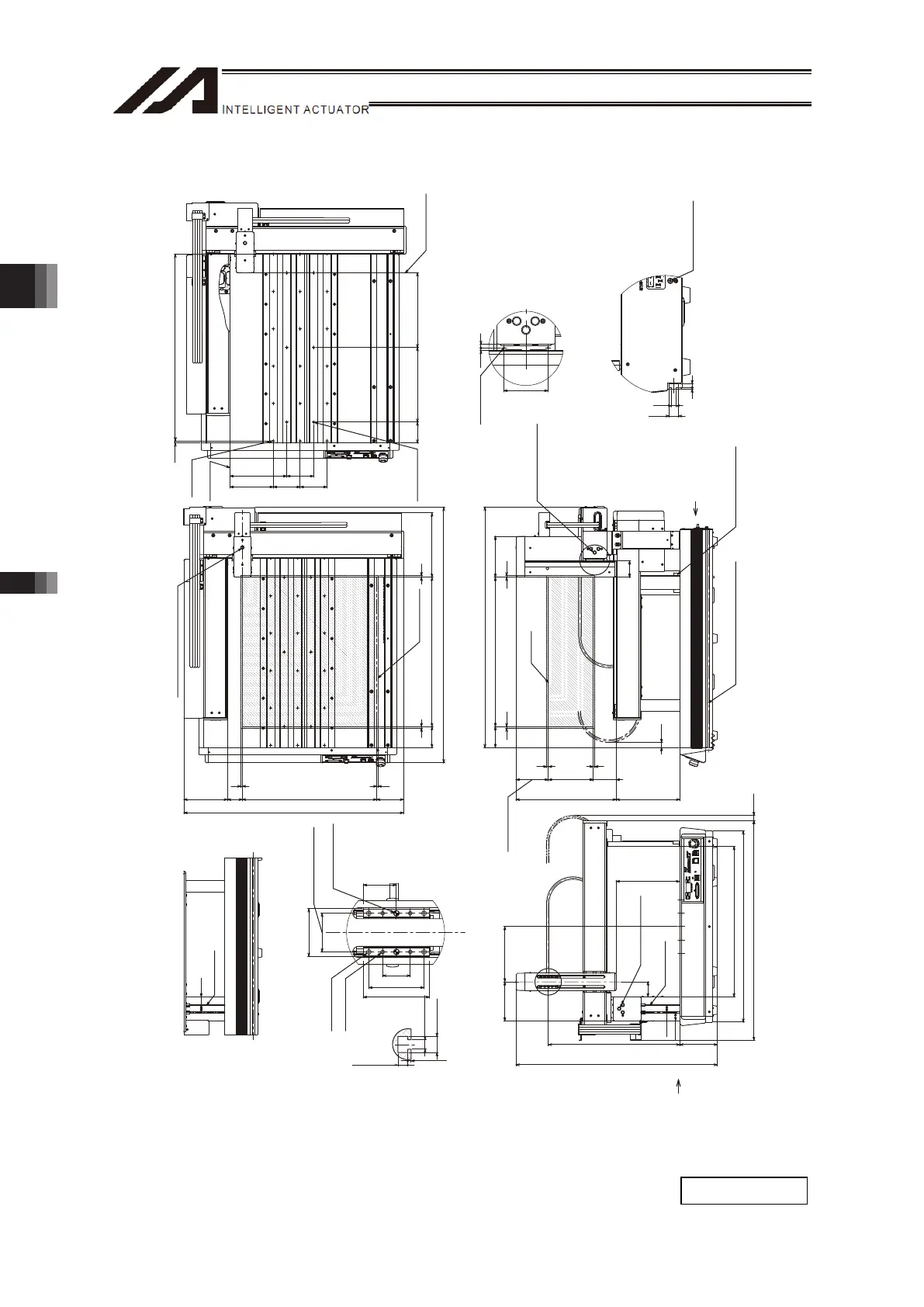
[8] Three-Axis: X- Axis 500mm Stroke, Y-Axis 450mm Stroke, Z-Axis 100mm/150mm Stroke
4.3
7.3
1.5
4.5
Xst: 500
Zst:100
Zst:
150
5
Zst=100:158.5
Zst=150:108.5
5
77
70
(17)
5 5
137.2
335.5
(213)
805
55
ME
SE
ME
ME SE ME
Y
27.5
25
185
(16.8)
736
640
131
674.5
126
Zst=100:390
Zst=150:440
503
213
50
U
Yst: 450
Xst: 500
90
5
70
5 5
5
215.5
50
(736)
854.7
146
SEME
ME
ME
SE
ME
25
50
60
35
43
30
27.5
25
145.59090
190.590
7.5 5x125p=625
70 250 250
3 7
8
16.5
60
3.5 5
2-φ5 H7 Depth 5
(Reamer Pitch
Tolerance ±0.02)
T-Groove ×2
4-M5 Depth 7
4-M4 Depth 7
Profile of T-Groove
on Frame
Detail Diagram U (Detail of Z-Axis Slider)
Dial for X-Slider
Position Tuning
X View
T-Groove ×2
X View
Operating Range
HOME
HOME
Dial for Z-Slider Position Tuning
V View
Frame Datum Surface
T-Goove
(Same Profile on Opposite Side)
HOME
HOME
Dial for Y-Slider
Position Tuning
Operating
Range
M4 for Grounding
V View (Grounding Screw)
SE: Stroke end
ME: Mechanical end
2-M3 Depth 6
Detail Diagram Y
(Side Surface of Y-Axis Slider)
(Same Profile on Opposite Side)
18-M5 Depth 10
Frame
Datum Surface
6-φ 5
H7 Depth 5
View for Top Base Hole Allocation
Pin Hole and
Z Slider Position
Mass: 51.3kg

 Loading...