93
[2] Example for Composition of Emergency Stop and Enable Circuits
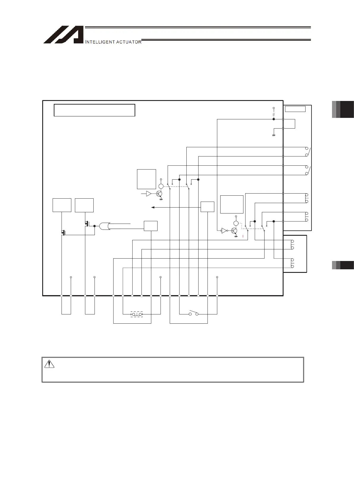
Shown below is an example for how to composite the emergency stop circuit and enable circuit.
[Example for Wiring when External Switch Installed (Standard Specification)]
TP
9. EMGS 1-
10. EMGS1+
7. EMGS 2-
8. EMGS 2+
12. EMGIN
3. ENBS 1-
4. ENBS 1+
1. ENBS 2-
2. ENBS 2+
6. ENBIN
11. EMGOUT
5. ENBOUT
VP24S VP24S
12.
EMGS1+_TP
13.
EMGS1- _TP
16.
EMGS2+_TP
24.
EMGS2- _TP
17.
ENBS 1+_TP
19.
ENBS 1- _TP
3
24
3
24
21.
ENBS 2+_TP
22.
ENBS 1- _TP
6
57
6
57
4. RTS
5. CTS
R
Y
R
Y
2- 3, 5- 6
: MANU
3- 4, 6- 7
: AUTO
ENBOK
MPO_A
MPI_A
24V
AUTO
/ TCPS
EMG SW
/ SDWN
MPO_B
MPI_B
24V
3rd, 4th axis 1st, 2nd axis
Motor Drive
Circuit
Motor Drive
Circuit
EMG
ENB
Status
Detection
Status
Detection
2-3, 5-6
: TP Connected
3-4, 6-7
: TP Unconnected
Enable SW
Emergency
Stop SW
Emergency Stop and Enable Circuits: Example for Wiring when External Switch Installed
(Standard
Specification
)
Caution: When using DP-1 or CB-ST-E1MW050-EB, the enable line cannot construct a
circuit using an external power source. If it is desired to use an external power
source to the enable line, use TB-02, TB-01, SEL-T/TD or CB-ST-A1MW050-EB.
TTA AC Servo Motor Type
Chapter 3 Wiring 3.2 Power Supply, Emergency Stop Circuit and Enable Circuit

 Loading...