Chapter 1 Specications Check1.3 Electrical Specications
60
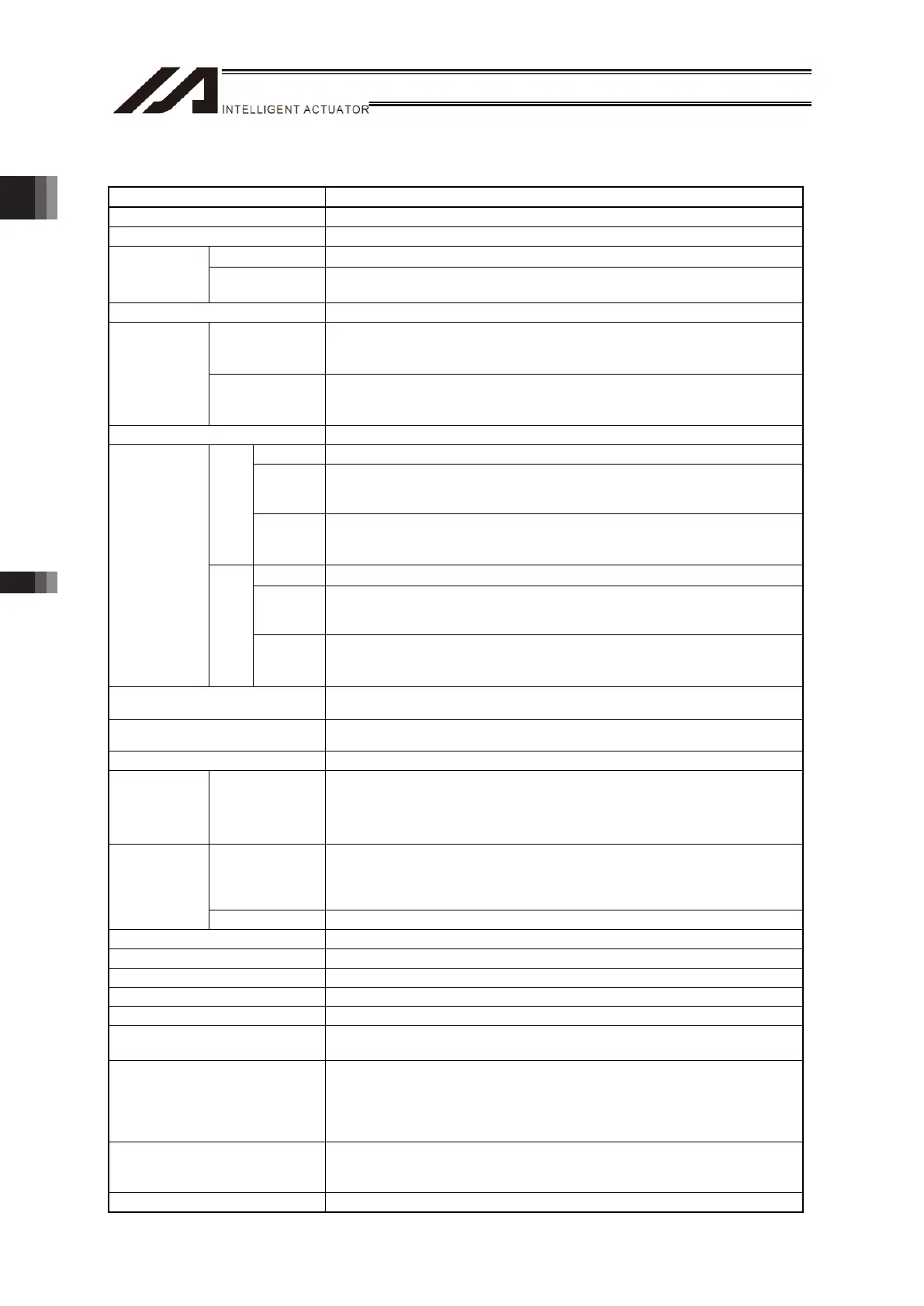
1.3 Electrical Specifications
Item Description
Power supply Voltage AC100 to 230V ±10%
Power Supply Frequency Range 50/60Hz ±5%
Pulse Motor 2.9A/1.2A (AC100/230V, when rated load)
Current
Consumption
Servo Motor
2-axis type: 2.9A/1.2A (AC100/230V, when rated load)
3-axis, 4-axis type: 5.8A/2.4A (AC100/230V, when rated load)
Service Power Output (For I/O) 24V DC ±10% MAX. 1A
Pulse Motor
At 100V AC: 15A Typ.
At 200V AC: 30A Typ.
(Surrounding temperature 25℃, No repeating of AC ON/OFF)
Rush Current
Servo Motor
At 100V AC: 30A Typ.
At 200V AC: 60A Typ.
(Surrounding temperature 25℃, No repeating of AC ON/OFF)
Transient Power Cutoff Durability 20ms
Voltage DC24V (Built-in Power Source)
Rated
Current
2-axis type: 4A
3-axis type: 6A
4-axis type: 8A
Pulse
Motor
Peak Max.
DC Current
Output
2-axis type: 8A
3-axis type: 12A
4-axis type: 16A
Voltage DC24V
Rated
Current
2-axis type: MPO_A 7A, MPO_B 0A
3-axis type: MPO_A 7A, MPO_B 4A
4-axis type: MPO_A 7A, MPO_B 8A
Motor Drive
Power Supply
Line
(Between MPI
and MPO)
Servo
Motor
Peak Max.
DC Current
Output
2-axis type: MPO_A 16A, MPO_B 0A
3-axis type: MPO_A 16A, MPO_B 8A
4-axis type: MPO_A 16A, MPO_B 16A
Emergency Stop Input (EMGIN),
Enable Input (ENBIN)
DC24V/10mA or less
Contact Output (EMGS1+/-,
EMGS2+/-, ENBS1+/-, ENBS2+/-)
DC30V/0.5A or less
Motor Control System Weak field-magnet vector control
Serial
Communication
Interface
(SIO Port)
Teaching Port
Connector dedicated for teaching tool
(Serial communication protocol (format B)
Connector: D-sub25-pin, USB B connector
Baud rate: 9.6、19.2、38.4、57.6、76.8、115.2kbps
Max. cable length: 10m (RS232C), 5m (USB)
PIO Type
Signal I/O dedicated for 24V DC (Selected from NPN/PNP)
• • • 16 points of input, 16 points of output
When extension DIO mounted: 48 points of input, 48 points of output
Cable length Max.100m
External
Interface
Field Network Type DeviceNet, CC-Link, PROFIBUS-DP, EtherNet/IP, EtherCAT, RS232C, RS485
Data Setting and Input PC software or teaching pendant
Data Retention Memory Position data and parameters are saved in the nonvolatile memory
Number of Programs 255
Number of Program Steps 9999
Number of Multitask Programs 16
Number of Positions
30000 points
(Note) 10000 points for system memory backup
LED Display
(Allocated on Front Panel)
RDY (Green): PIO program operation available
ALM (Orange): Error in operation cancel level or more generated
EMG (Red): In emergency stop
HPS (Green): Home-return operation completed on all axes
CKE (Orange): System lock error
Z-Axis Electromagnetic Brake
Compulsory Release Switch
(Allocated on Front Panel)
Switchover of NOM (normal) / BK RLS (compulsory release)
Insulation Resistance Between secondary – FG 500V DC 10M or more

 Loading...