Chapter 9 External Dimensions9.1 Servo Motor Type, Pulse Motor Type (Battery-less Absolute Specication)
326
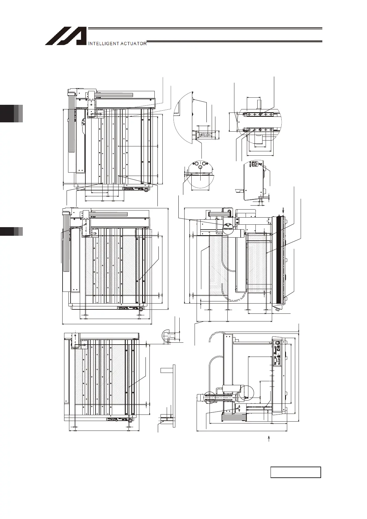
[12] Four-Axis: X- Axis 500mm Stroke, Y-Axis 450mm Stroke, Z-Axis 100mm/150mm Stroke
18-M5
Depth 10
Frame
Datum
Surface
6-φ 5
H7 Depth 5
View for Top Base Hole Allocation
Pin Hole and
Z Slider Position
R Spline Position
4.3
7.3
1.5
4.5
Zst:100
Zst:150
Xst: 500
5
Zst:100
Zst:150
5
Zst=100:100
Zst=150: 50
5 5
70
90
5 5
5
75
5
375
137.2
Zst=100:158.5
Zst=150:108.5
805
ME
SE
ME
ME
SE
ME
SE
ME
ME SE ME
ME
Y
Zst=100:475
Zst=150:525
759.5
739.7
503
126
640
25
27.5
U
W
Yst: 450
Xst: 500
5
70
5
55
90 50
854.8
SE
ME
ME
SE
ME
ME
590
145.5
190.590
9090
7.5 5x125p= 625
70 250 250
140
35
60
43
25
50
30
2-φ 5 H7
8
16.5
3 7
20
φ 10 h7
19
Xst: 50090
Yst: 450
5 5
90
5 5
50
MESEME
ME
SE
ME
27.5
25
60
3.5 5
(Xst:500)
(17)
(16.8)
(200)
(50)
(140)
(755.8)
HOME
R-Slider
Operating Range
R-Slider
Operating Range
T-Groove
×2
X View
T-Groove
×2
X View
Dial for Z-Slider
Position Tuning
Profile of T-Groove
on Frame
HOME
HOME
HOME
HOME
R-Slider
Operating Range
Z-Slider
Operating Range
T-Goove (Same Profile on Opposite Side)
Dial for Y-Slider
Position Tuning
Frame Datum Surface
V View
HOME
HOME
Dial for Z-Slider
Position Tuning
Z-Slider
Operating Range
2-M3
Depth 6
Dial for R-axis
Rotation
Position Tuning
R-axis
Datum
Surface
Detail Diagram W
(Detail of R-Spline tip end)
M5 Depth 10
Detail Diagram Y
(Side Surface of Y-Axis Slider)
(Same Profile on Opposite Side)
(Reamer Pitch
Tolerance ±0.02)
Depth 5
4-M5 Depth 7
4-M4 Depth 7
Detail Diagram U
(Detail of Z-Axis Slider)
SE: Stroke end
ME: Mechanical end
V View (Grounding Screw)
M4 for
Grounding
Mass: 53.3kg

 Loading...