91
3.2.2 AC Servo Motor Type
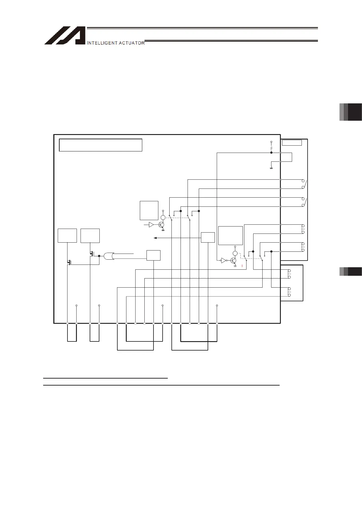
[1] Internal Circuit Composition
[Standard Specification]
• All the motor drive power supply lines are cut off by FET.
• Switchover of active/inactive on the emergency stop line on the connector for teaching can be
performed with the bypass relay by detecting the connection of connector for teaching.
• Switchover of active/inactive on the enable switch line on the connector for teaching can be
performed with the bypass relay by operating the mode switch.
TP
9. EMGS 1-
10. EMGS 1+
7. EMGS 2-
8. EMGS 2+
12. EMGIN
3. ENBS 1-
4. ENBS1+
1. ENBS 2-
2. ENBS2+
6. ENBIN
11. EMGOUT
5. ENBOUT
VP 24S
VP 24S
12.
EMGS1+_TP
13.
EMGS1- _TP
16.
EMGS2+_TP
24.
EMGS2- _TP
17.
ENBS1+_TP
19.
ENBS1- _TP
3
24
3
24
21.
ENBS2+_TP
22.
ENBS1- _TP
6
57
6
57
4. RTS
5. CTS
R
Y
R
Y
2- 3, 5- 6
: MANU
3- 4, 6- 7
: AUTO
ENBOK
MPO_ A
MPI_ A
24 V
AUTO
/ TCPS
EMG SW
/ SDWN
MPO_ B
MPI_ B
EMG
ENB
3rd, 4th axis 1st, 2nd axis
Status
Detection
Status
Detection
Motor Drive
Circuit
Motor Drive
Circuit
2-3, 5-6
: TP Connected
3-4, 6-7
: TP Unconnected
Emergency Stop, Enable Internal Circuit and External Wiring at Delevery
* 24V DC/10mA or less for EMGIN and ENBIN
* Contact output (EMGS1+/-, EMGS2+/- and ENBS2+/-) should be 30V DC/0.5A or less.
TTA AC Servo Motor Type
Chapter 3 Wiring 3.2 Power Supply, Emergency Stop Circuit and Enable Circuit

 Loading...