116
[1] RS232C Interface
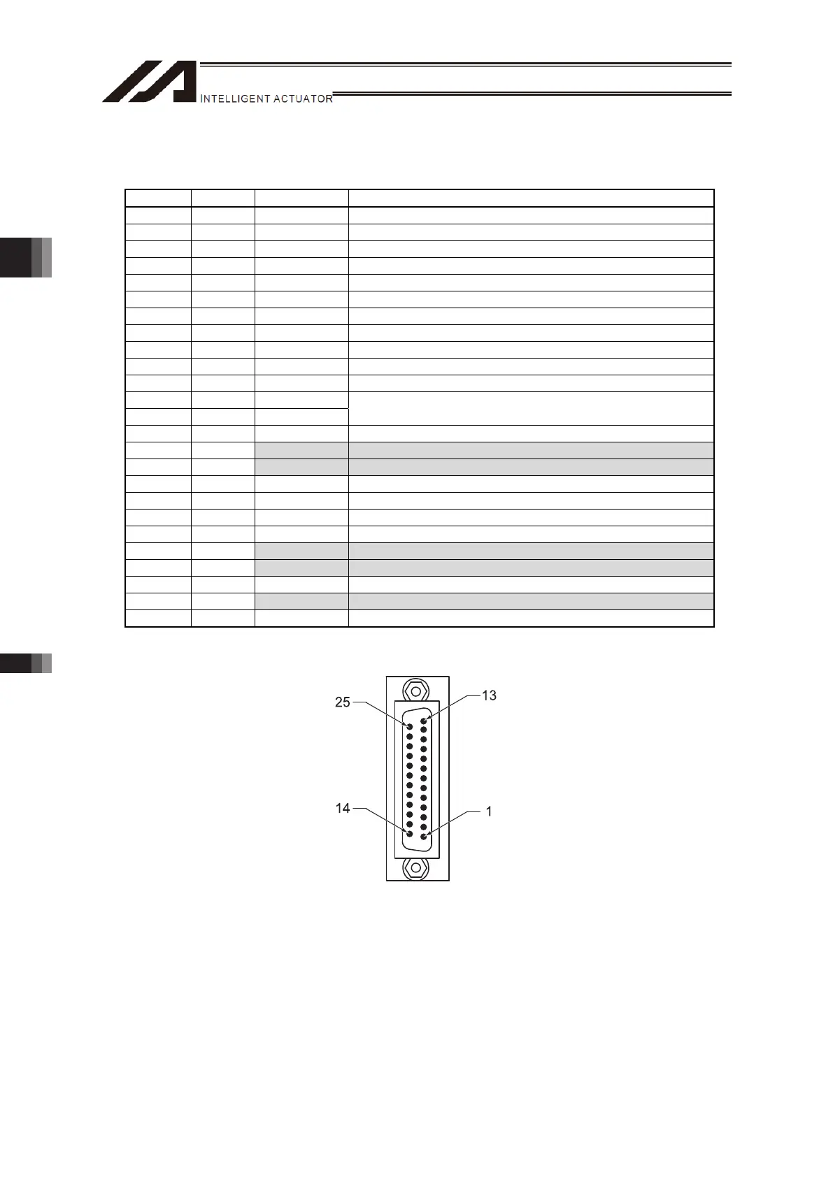
Terminal Assignments
Pin No. Direction Signal Name Description
1 FG Frame ground
2 Out TXD Transmit data
3 In RXD Receive data
4 Out RTS Request to send
5 In CTS Clear to send
6 Out DSR Equipment ready
7 SG Signal ground
8 NC Not connected
9 In RSVTBX1 Not used
10 In RSVTBX2 Not used
11 NC Not connected
12 Out EMGOUT1
13 In EMGIN1
Emergency stop contact 1
14 NC Not connected
15 Out RSVVCC 24V teaching pendant power
16 Out EMGOUT2 Emergency stop contact 2
17 Out ENBVCC1 Enable drive power 1
18 Out VCC Power output (teaching pendant power)
19 In ENBTBX1 Enable input 1
20 In DTR Terminal ready
21 Out ENBVCC2 Enable drive power 2
22 In ENBTBX2 Enable input 2
23 Out EMGS Emergency stop status
24 In EMGIN2 Emergency stop contact 2
25 SG Signal ground
The shaded signals are supported by IA-101-XA-MW teaching pendants TB-02D, TB-01D,
SEL-TD only.
Chapter 3 Wiring3.4 Wiring Method

 Loading...