Chapter 1 Specications Check1.2 Mechanical Specications
52
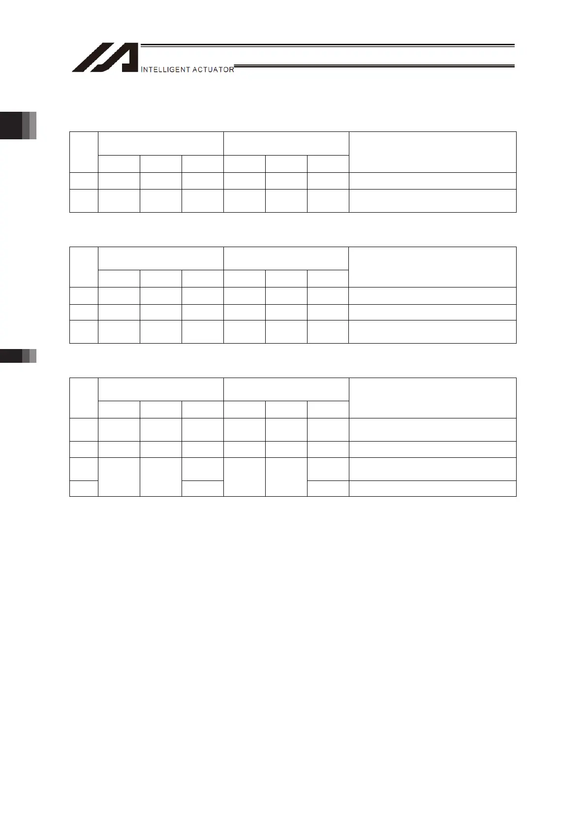
[4] Work Fixing Type Servo Motor Specifications
• 2-Axis Type
Allowable Static Load
Moment [N•m]
Allowable Dynamic Load
Moment [N•m]
Axis
Ma Mb Mc Ma Mb Mc
Overhang load length [L]
X 47.9 47.9 142.1 14.9 14.9 44.3 -
Y 47.9 47.9 142.1 14.9 14.9 44.3
Ma direction: 170mm or less
Mb or Mc direction: 210mm or less
• 3-Axis Type
Allowable Static Load
Moment [N•m]
Allowable Dynamic Load
Moment [N•m]
Axis
Ma Mb Mc Ma Mb Mc
Overhang load length [L]
X 47.9 47.9 142.1 14.9 14.9 44.3 -
Y 47.9 47.9 142.1 14.9 14.9 44.3 -
Z 35.0 35.0 74.0 11.5 11.5 24.3
Ma direction: 75mm or less
Mb or Mc direction: 180mm or less
• 4-Axis Type
Allowable Static Load
Moment [N•m]
Allowable Dynamic Load
Moment [N•m]
Axis
Ma Mb Mc Ma Mb Mc
Overhang load length [L]
X 47.9 47.9 142.1 14.9 14.9 44.3
Ma direction: 190mm or less
Mb or Mc direction : 240mm or less
Y 47.9 47.9 142.1 14.9 14.9 44.3 -
Z 74.0 24.3
Ma direction: 75mm or less
Mb or Mc direction: 180mm or less
R
35.0 35.0
-
11.5 11.5
- Radius 100mm or less:
* Refer to “1.2.7 Ma Direction Moment Offset Datum Position and Each Axis Moment Direction” for the
Ma direction moment offset datum position and the moment direction of each axis.
* It is the value assuming the rated life of the linear guide is 5,000km (fw: 1.5, remaining ratio 90%).
* Z and R-axes allowable moments Ma and Mb for the four-axis type should be the sum total of Z-axis
and R-axis.

 Loading...