Chapter 1 Specications Check 1.1 Product Check
35
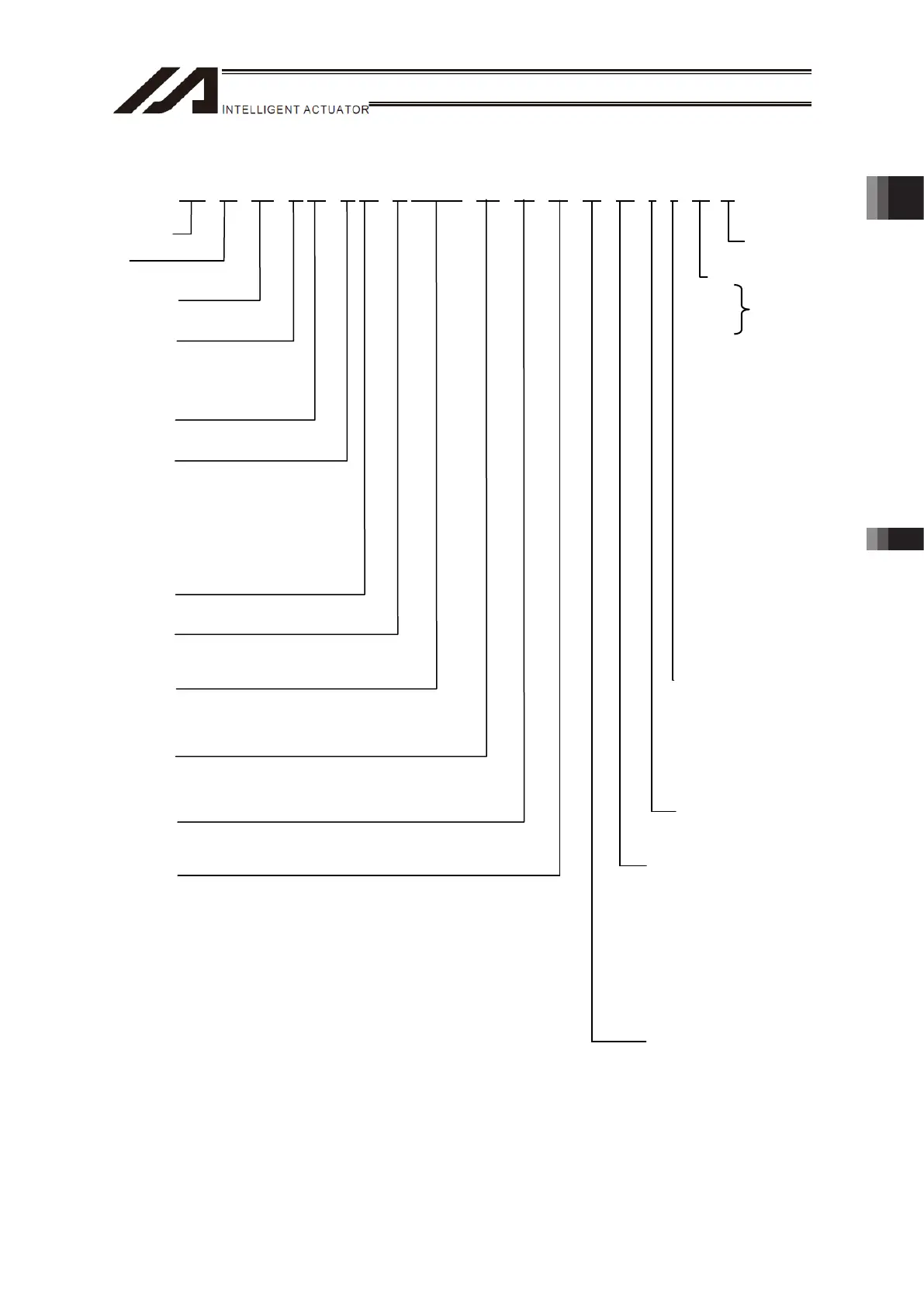
1.1.4 How to Read the Model
TTA – A3 – WA – 30 HS – 30 HS – 15 BHSNM – 36L – ML – NP – DV – EP – 2 – 1 – H1 - * *
<Series Name>
<Type>
* 1 Refer to type of next page
<Encoder Type>
WA : Battery-less Absolute
<X-Axis Stroke>
20: 200mm
30: 300mm
40: 400mm
50: 500mm
<X-Axis Option>
NM: Reversed-home specification
<Y-Axis Stroke>
20: 200mm (Work Moving Type)
30: 300mm (Work Moving Type)
40: 400mm (Work Moving Type)
50: 500mm (Work Moving Type)
15: 150mm (Work Fixing Type)
25: 250mm (Work Fixing Type)
35: 350mm (Work Fixing Type)
45: 450mm (Work Fixing Type)
<Y-Axis Option>
NM: Reversed-home specification
<Z-Axis Stroke>
10: 100mm
15: 150mm
<Z-Axis Option>
B: Brake (Nomal)
CO: With Cover (Dedicated for 4-axis specification)
NM: Reversed-home specification
<R-Axis Stroke>
18 : ±180deg (Battery-less Absolute Type)
18L: ±180deg (Incremental Type)
36L: ±360deg (With Home limit switch)
<R-Axis Option>
ML: Motor left reversed (Standard)
MR: Motor right reversed
<Standard Slot>
NP:NPN type
PN:PNP type
Identification for IAI
use only
(Note 1)
<Option>
H1: Y-axis mount
H2: position change
F1: Refer to next page
F2:
FT4: Main-unit bracket-
equipped type
(with 4 pieces of
brackets)
FT6: Main-unit bracket-
equipped type
(with 6 pieces of
brackets)
AP: Support added for 2020
type
OS: Detachable operation
unit type
SLT0: Side slot 180mm
SLT: Side slot for each
stroke
PTH: Side plate (with hole)
PTN: Side plate (With no
hole)
FZ: ZR-axis mounting
position 64.5mm
forward
* 2: Refer in the next page for
model code for additional
switch
<Power Supply Cable Specifications>
PU: Only with plug on main unit side
1: Power supply cable for 100V AC
(2m)
(with 3-pin plug on one end)
2: Power supply cable for 200V AC
(2m)
(Ring tongue terminal on one side)
<I/O Cable Length>
0: None, 2: 2m
3: 3m, 5: 5m
<Extension Slot 2>
E: Not use
NP: Extension I/O board (NPN type)
PN: Extension I/O board (PNP type)
DV: DeviceNet connection board
CC: CC-Link connection board
PR: PROFIBUS-DP connection board
EP: EtherNetI/P connection board
(Note 2)
EC: EtherCAT connection board
(Note 4)
IA
: IA-NET connection board
(Note 5)
SE1: RS232C connection board
SE2
: RS485 connection board
<Extension Slot 1>
E: Not use
NP:Extension I/O board (NPN type)
PN:Extension I/O board (PNP type)
DV: DeviceNet connection board
CC:CC-Link connection board
PR:PROFIBUS-DP connection board
EP: EtherNet/IP connection board
(Note 2)
EC: EtherCAT connection board
(Note 4)
IA
: IA-NET connection board
(Note 5)
SE1: RS232C connection board
SE2
: RS485 connection board
Note 1 It may be displayed for IAI use. (It is not a code to show the model type.)
Note 2 2 pieces of EtherNet/IP cannot be selected to the extension I/O slot.
If there are two extension I/O slots, Extension I/O Slot 2 can only be selected.
Note 3 The difference between each model is only the strokes of X/Y axes and Z-axis.
The driving system is constructed with the same motor.
Note 4 Two units of EtherCAT can be mounted on the extension I/O slot at the
maximum.
EtherCAT can be mounted on either of the extension I/O slots (when only one
unit) or on both of them.
Note 5 Only one unit of IA-NT can be mounted on either of the extension I/O slots.

 Loading...