Chapter 9 External Dimensions9.2 Pulse Motor Type (Incremental Specication)
336
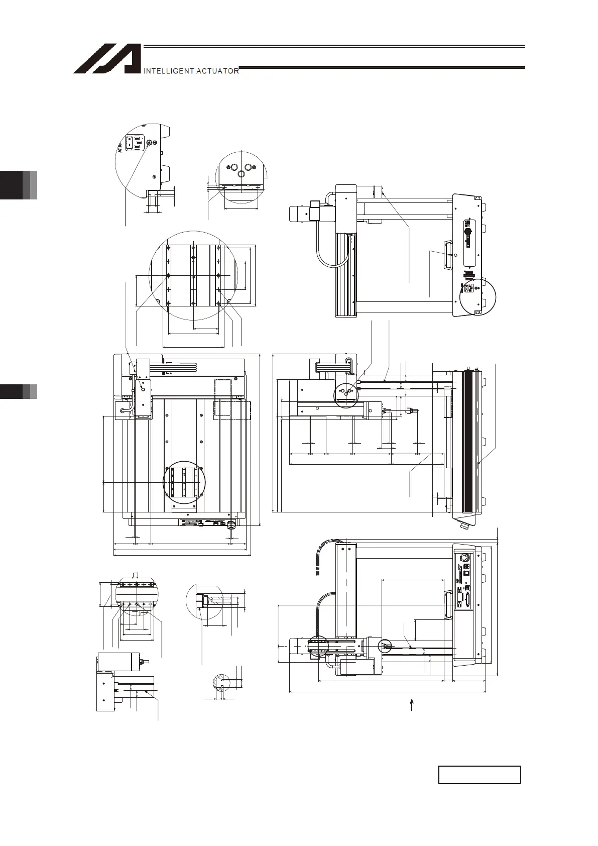
[10] Four-Axis: X & Y-Axes 300mm Stroke, Z- Axis 100mm/150mm Stroke
(12)
235.5
80
25
27.5
440
501
125 32
Zst=100:475
Zst=150:525
60 155
Zst=100:740.5
Zst=150:790.5
W
U
5
Zst: 100
Zst:150
75.5
Xst: 300
5
63
Zst: 100
Zst:150
5 5
145
Zst=100:100
Zst=150:50
55
362 137.2
595.5
348
55.5
89.5
57 110
35.5
Zst=100:383.5
Zst=150:433.5
60 78.5
(200)
25
27.5
55
HOME
HOME
ME
MESE
Y
V
5
Yst: 300
517
61
5
646.8
501
58 82
112 250
SE
ME
ME
S
16.5
8
3 7
20
φ
10 h7
19
43
35
60
50
25
30
4.51.5
4.3
7.3
25
27.5
45
110
55
50
100
110
90
3.5 5
60
Detail Diagram V (Grounding Screw)
M4 for Grounding
2-M3
Depth 6
Detail Diagram Y (Side Surface of Y-Axis Slider)
(Same Profile on Opposite Side)
Dial for X-Slider
Position Tuning
SE: Stroke end
ME: Mechanical end
Dial for Y-Slider
Position Tuning
T-Groove ×2
(Same Profile on
Opposite Side of Frame)
T-Goove (Same Profile on Opposite Side)
HOME:Z-Slider
ME:
Z-Slider
ME:
Z-Slider
SE:
Z-Slider
ME:Spline
ME:Spline
HOME:Spline
SE:Spline
X View
T-Groove
×2
Detail Diagram S (Detail of X-Axis Slider)
6-M5 Depth 7
6-M4 Depth 7
(Reamer Pitch
Tolerance ±0.02)
2-φ5 H7 Depth 5
Dial for Z-Slider Position Tuning
(R-axis on the Other Side)
Detail Diagram W
(Detail of R-axis tip end)
R-axis Datum Surface
4-M5 Depth 7
4-M4 Depth 7
(Reamer Pitch
Tolerance ±0.02)
2-φ5 H7 Depth 5
M5 Depth 10
X View
(T-Groove on Side of Main Unit)
T-Groove
×2
Profile of T-Groove
on Frame
Detail Diagram U
(Detail of Z-Axis Slider)
Volume for Position
Tuning in Turning Direction
Mass: 35kg

 Loading...