83
Chapter 3 Wiring
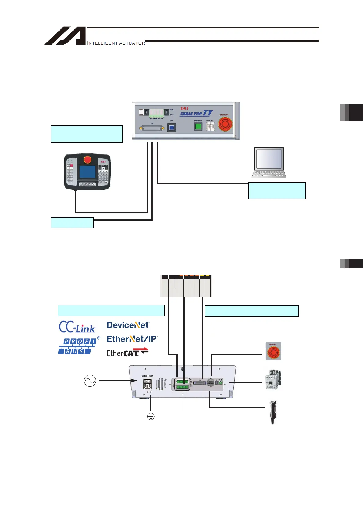
3.1 Wiring Diagram
* Emergency stop switch, enable switch, electromagnetic contactor and other considered devices are
to be in layout if necessary. Operation is available with the settings at delivery (short-circuit
treatment).
PL C
2m
5m
5m /3m
Front Panel Wiring Layout
Back Panel Wiring Layout
Variety of Field Network (Options)
IO Flat Cable (Accessories)
Model: CB-PAC-PIO020
Model: TB-01-S
Touch Panel Teaching
(Option)
Model: IA-101-X-MW
IA-101-TT-USB
IA-101-X-USBMW
IA-101-XA-MW
PC Software
(Option)
Emergency
Stop Switch
Electromagnetic
Contactor
Enable Switch
PC Connection Cable
(Enclosed in PC Software)
Model: CB-ST-E1MW050 (5m)
CB-SEL-USB030 (3m)
CB-ST-AIMW050 (5m)
AC100 to 230V
Select from those below
for power supply cable
• Only with plug on main
unit side
• Power supply cable
for 100V AC (2m)
• Power supply cable
for 200V AC (2m)
Protective
Grounding
Extension
I/O Slot
Standard I/O Service
Power Supply
Connector
Dummy Plug
Model: DP-2
* Enclosed in global type and PC Software (IA-101-TTA-USB)
Chapter 3 Wiring 3.1 Wiring Diagram

 Loading...