84
3.2 Power Supply, Emergency Stop Circuit and Enable Circuit
With the wiring to the inlet and system I/O connectors, power supply circuit and safety circuit (external
and built-in emergency stop circuit and external enable circuit) can be constructed.
Safety circuit is a circuit that is to be prepared to stop the robot operation manually to prevent any
accident in advance when an operator gets to feed dangerous. The Machinery Directive (MD) requests
Safety Category 3 or higher.
If Machinery Directive is required, refer to 3.2.2 [5] below to construct yourself an external safety circuit.
Have a strand with wire diameter 0.5mm
2
(AWG20 or equiv.) or more for those interconnection cables.
3.2.1 Pulse Motor Type
[1] Internal Circuit Composition
[Standard Specification]
• All the motor drive power supply lines are cut off by FET.
• Switchover of active/inactive on the emergency stop line on the connector for teaching can be
performed with the bypass relay by detecting the connection of connector for teaching.
• Switchover of active/inactive on the enable switch line on the connector for teaching can be
performed with the bypass relay by operating the mode switch.
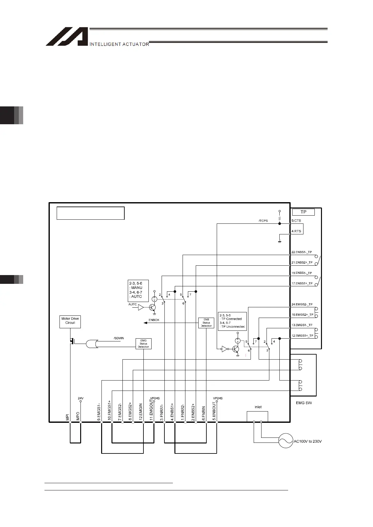
Emergency Stop, Enable Internal Circuit and External Wiring at Delevery
* 24V DC/10mA or less for EMGIN and ENBIN
* Contact output (EMGS1+/-, EMGS2+/- and ENBS2+/-) should be 30V DC/0.5A or less.
TTA Pulse Motor Type
Chapter 3 Wiring3.2 Power Supply, Emergency Stop Circuit and Enable Circuit

 Loading...