22
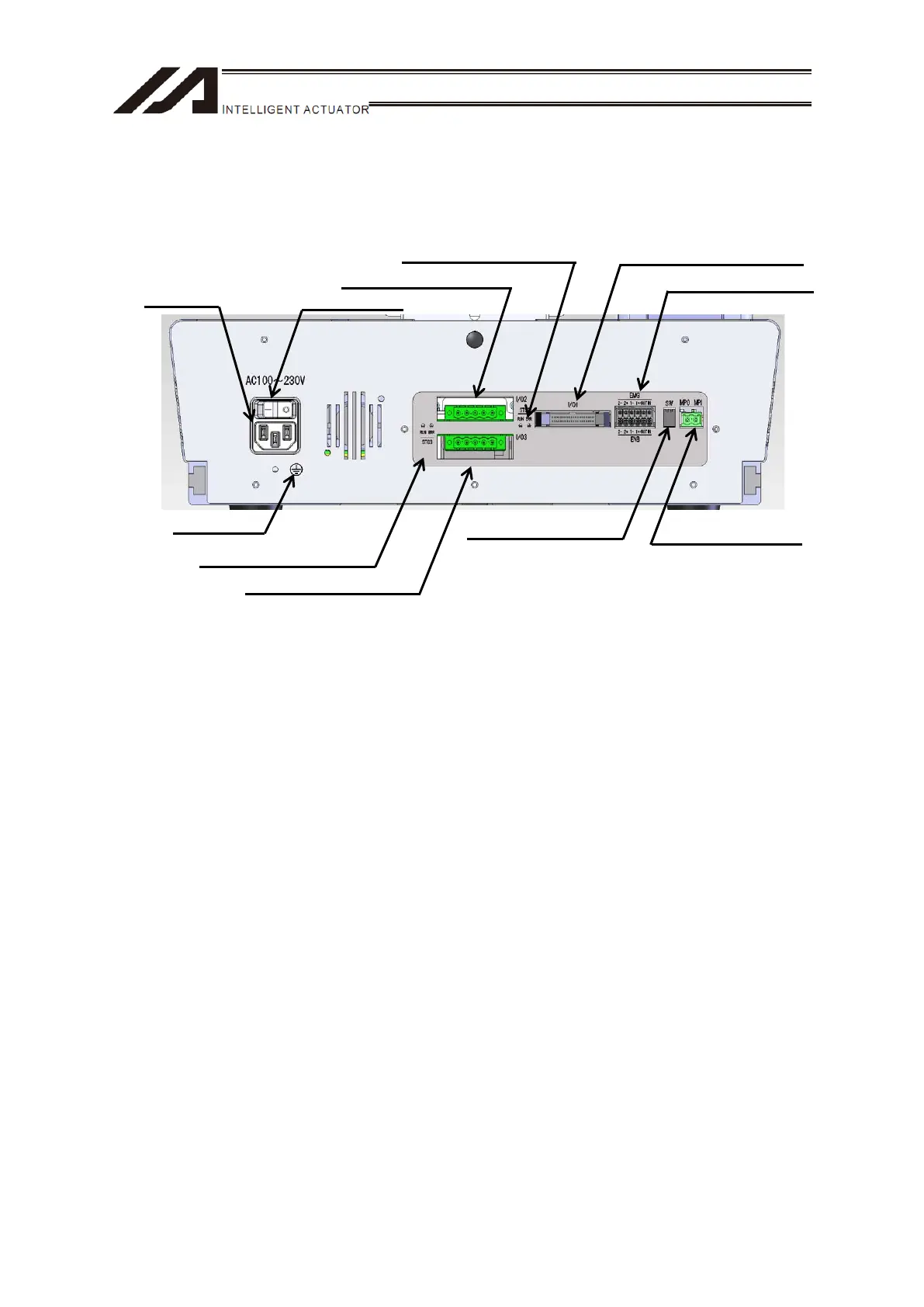
<Details of Rear Panel>
9) AC Inlet
Connect the power supply cable.
Apply the enclosed socket on the power supply connector.
(Note) Make sure to prepare a cable suitable for the power voltage used to the enclosed socket for
wiring.
Input power voltage range: 100 to 230V AC ±10%
10) Power Switch
It is a switch to turn the main power supply ON/OFF.
11) Expanded I/O Slot 1 (I/O2)
17) Expanded I/O Slot 2 (I/O3)
With the combination of extension DIO, DeviceNet, CC-Link, PROFIBUS-DP and EtherNet/IP etc,
two modules at the maximum are available to mount. (However, only EtherNet/IP is one module.)
13) Standard I/O Service Power
Supply Connector
16) Service Power Switch
14) System I/O Connector
19) FG Terminal
9
AC Inlet
15) Motor Power Supply
Connector
10) Power Switch
17) Expanded I/O Slot 2 (I/O3)
11
Ex
anded I/O Slot 1
I/O2
18) Expanded I/O Slot 2 (I/O3)
Status LED
12) Expanded I/O Slot 1 (I/O2)
Status LED

 Loading...