89
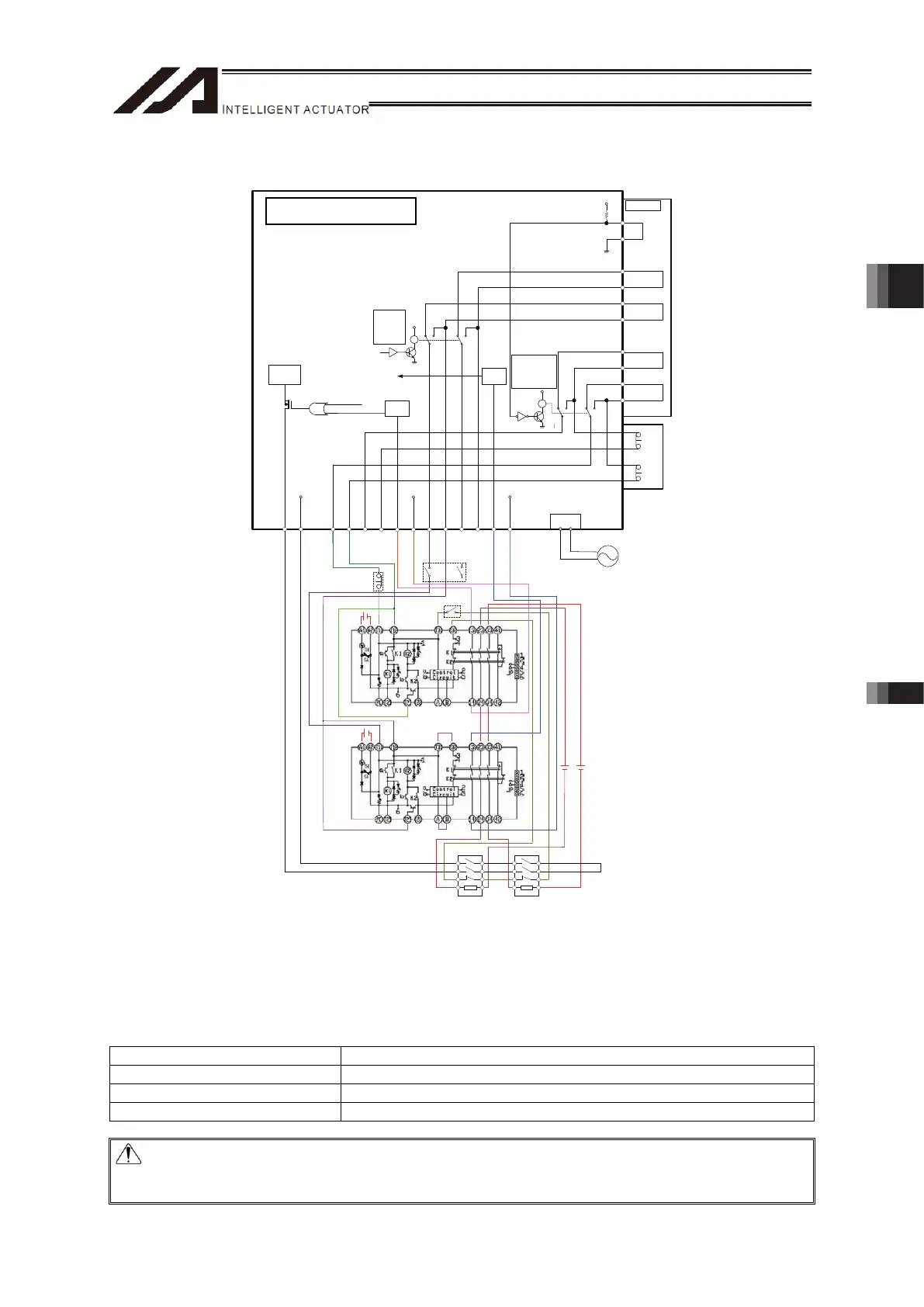
[Emergency Stop and Enable Circuits: Example for Wiring Considering Safety Category 2]
DP-2
12.EMGS1+_TP
13.EMGS1-_TP
16.EMGS2+_TP
24.EMGS2-_TP
17.ENBS1+_TP
21.ENBS2+_TP
22.ENBS1-_TP
4.RTS
5.CTS
EMG SW
V42V42
9.EMGS
1-
10.EMGS1+
7.EMGS2-
8.EMGS2+
12.EMGIN
3.ENBS1
-
4.ENBS1+
1.ENBS2-
2.ENBS2+
6.ENBIN
11.EMGOUT
5.ENBOUT
VP24S VP24S
3
24
3
24
6
57
6
57
2-3, 5-6
: TP
Connected
3-4, 6-7
: TP
Unconnected
R
Y
R
Y
2-3, 5-6
: MANU
3-4, 6-7
: AUTO
EMG
Status
Detection
ENB
Status
Detection
ENBOK
MPO
MPI
Motor Drive
Circuit
24V
AUTO
/TCPS
TTA
/SDWN
Reset SW
Enable SW
Emergency
Stop SW
G9SA-301
(OMRON)
G9SA-301
(OMRON)
Electromagnetic
Contactor
Electromagnetic
Contactor
24V
24V
System I/O
Connector
24V24V
Inlet
AC100V to 230V
19.ENBS1-_TP
Emergency Stop and Enable Circuits: Example for Wiring Considering Safety Category 2
* Regarding the contact in connector area for teaching, there is a bypass relay connected, thus it
cannot be used as a safety circuit. (It can be applicable with a special order of “with no bypass”
when using a contact on the connector area for teaching. In such a case, use a dummy plug (DP-2)
when the connector for teaching is not to be in use.)
* The power supply specifications between the terminals for MPO and MPI are as described below.
Specification
Voltage DC24V (Built-in Power Source)
Rated Current 2-axis type: 4A, 3-axis type: 6A, 4-axis type: 8A
Peak Max. DC Current Output 2-axis type: 8A, 3-axis type: 12A, 4-axis type: 16A
Caution: When using DP-1 or CB-ST-E1MW050-EB, the enable line cannot construct a circuit
using an external power source. If it is desired to use an external power source to the
enable line, use TB-02, TB-01, SEL-T/TD or CB-ST-A1MW050-EB.
TTA Pulse Motor Type
Chapter 3 Wiring 3.2 Power Supply, Emergency Stop Circuit and Enable Circuit

 Loading...