FLIGHT CONTROLS / ROLL CONTROLS 9-15
CHANGE C3 ICON A5 / MAINTENANCE MANUAL
6. Install .1875 in diameter rig pin through the control stick rig pin hole. See Figure 9-10.
FIGURE 9-10
CONTROL STICK RIG PIN LOCATION
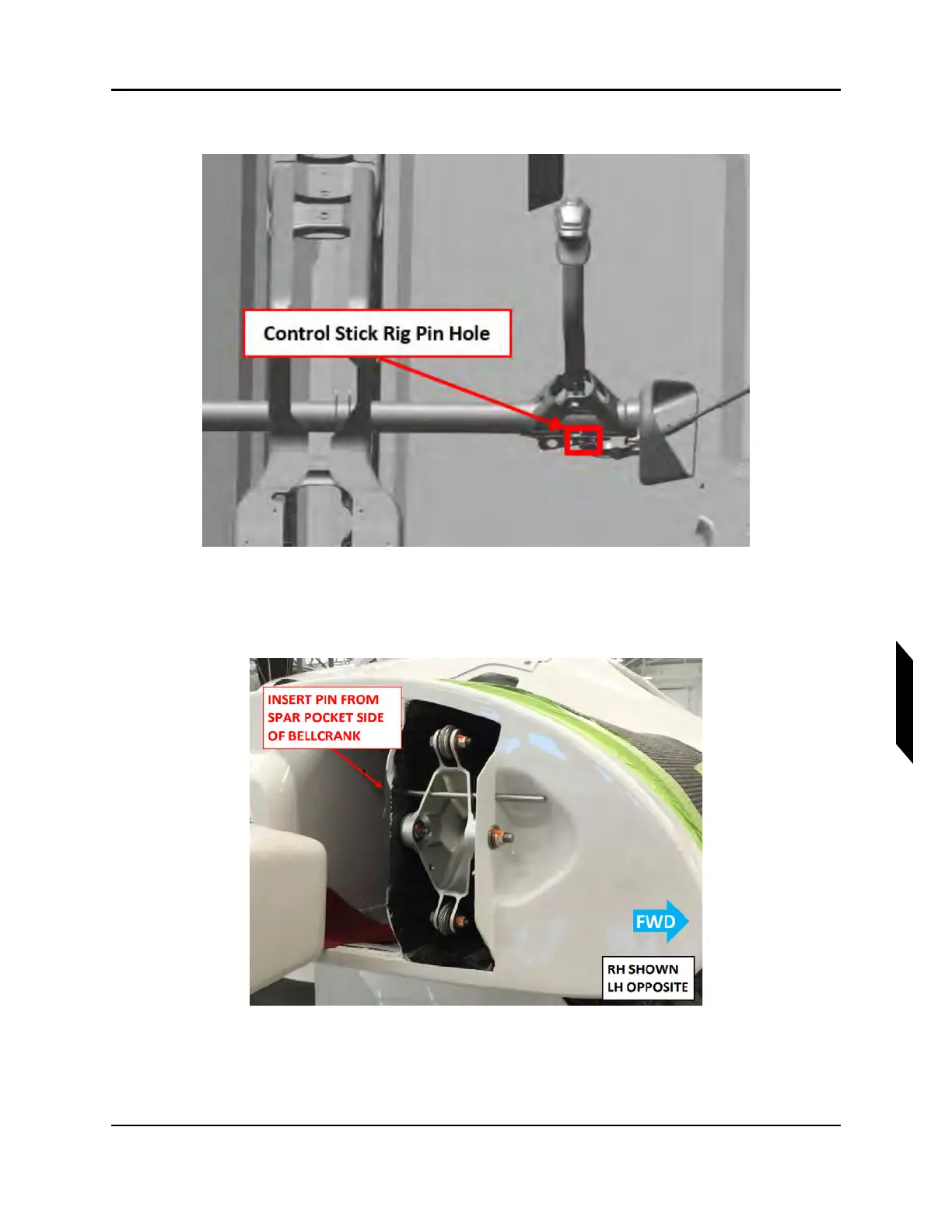
7. Fold both aircraft wings and install a .1875in diameter rig pins at both of the wing socket bell-
crank. See Figure 9-11.
FIGURE 9-11
WING SOCKET BELLCRANK RIG PIN LOCATION
8. Use the tensiometer (upper cable thickness = 3/32 in, LH and RH fuselage cable thickness = 1/8
in) to measure roll cable tension at locations specified in, see Figure 9-12. Ensure they all are